OpenPLC Editor for CONTROLLINO
Introduction In the world of industrial automation, having an intuitive and powerful programming environment is key. OpenPLC Editor, combined with CONTROLLINO, brings a seamless IEC
More information about port manipulation on this site: https://www.arduino.cc/en/Reference/PortManipulation
Port registers allow for lower-level and faster manipulation of the i/o pins of the microcontroller on an Controllino PLC. Each port is controlled by three registers, which are also defined variables in the arduino language:
DDR and PORT registers may be both written to, and read. PIN registers correspond to the state of inputs and may only be read.
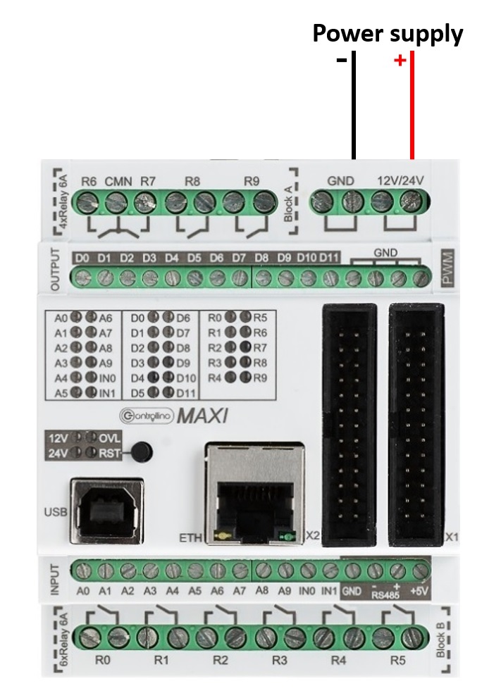
There is the possibility to parallelize some digital outputs to drive loads with the need of more current under the following conditions:
MINI
1st group: D0, D1, D2, D3
2nd group: D4, D5
3rd group: D6, D7
MAXI:
1st group: D0, D1, D3
2nd group: D2
3rd group: D4, D5, D6, D7
4th group: D8, D9, D10, D11
MEGA:
1st group: D0, D1, D3
2nd group: D2
3rd group: D4, D5, D6, D7
4th group: D8, D9, D10, D11
5th group: D12, D13, D14, D15, D16, D17, D18, D19
6th group: D20, D21, D22
7th group: D23
In order to see which Controllino pin corresponds to which PORT on microprocessor open the Controllino PINOUT tables.
Link to PINOUT table is here.
IMPORTANT INFORMATION!
Please, select proper target board in Tools->Board->Controllino MINI/MAXI/MEGA before Upload to your CONTROLLINO.
(Please, refer to https://github.com/CONTROLLINO-PLC/CONTROLLINO_Library if you do not see the CONTROLLINOs in the Arduino IDE menu Tools->Board.)
Note*
Pin header is working on 5V TTL levels. Voltage levels over 5.5V can damage the Controllino permanently.
To check where is the Overload LED connected we open the PINOUT table of the Controllino and find it.
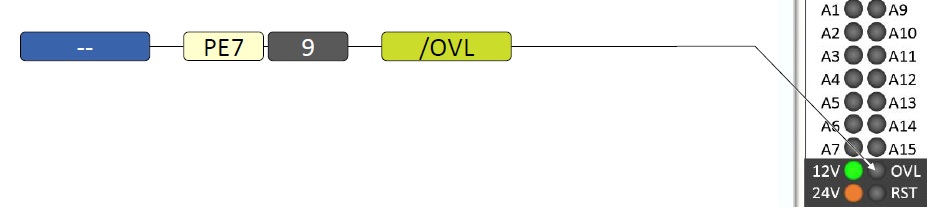
Here we can see that the OVL LED is connected to the 7th bit of the PORT E on ATmega2560. There is no arduino number for this pin so we cannot set it like other arduino i/o pins.
The manipulation of this pin is shown in the next example:
void setup()
{

 //Define the LED as an OUTPUT
 DDRE = DDRE | B10000000;

}

void loop()
{

 //Set the 7th bit of the PORT E to HIGH without influence on other bits (OR logic)
 PORTE = PORTE | B10000000;
 delay(1000);
 //Set the 7th bit of the PORT E to LOW without influence on other bits (AND logic)
 PORTE = PORTE & B01111111;
 delay(1000);

}
To check the state of the Overload LED:
void setup()
{
 Serial.begin(9600);
 DDRE = DDRE & B01111111; //Set PE7 (OVL pin) as INPUT
 Serial.println("CONTROLLINO Overload read:");
}

void loop()
{
 Serial.print("Overload signal: ");
 int Overload_signal = PINE >> 7;
 if (Overload_signal == 1) Serial.println("OFF");
 else Serial.println("ON");
 delay(1000);
}