OpenPLC Water Reserve Control

Categories: , , , ,

Introduction

This tutorial explains how to implement an automatic water reserve control system using a CONTROLLINO PLC and OpenPLC. The system monitors the water levels of a cistern (minimum level) and an elevated tank (minimum and maximum levels) to control a pump that transfers water from the cistern to the elevated tank. Additionally, manual pump control is possible using start and stop buttons.

Prerequisites

Before starting, ensure you have the following:

  • OpenPLC software installed.
  • A CONTROLLINO PLC (any model) or a compatible PLC.
  • Sensors for water level detection:
  • Minimum level sensor for the cistern.
  • Minimum and maximum level sensors for the elevated tank.
  • Two buttons for manual control (Start and Stop).
  • Basic knowledge of ladder logic programming.

Step-by-Step Guide

Step 1: Install and Set Up OpenPLC

  1. Download OpenPLC:
  • Visit the OpenPLC official website and download the software.
  • Follow the installation instructions for your operating system.
  1. Set Up the OpenPLC Environment:
  • Open the OpenPLC editor.
  • Configure the device by selecting your CONTROLLINO model in Settings > Device.
  • Assign the correct COM port for communication with the PLC.

Step 2: Configure System Inputs and Outputs

Define the following inputs and outputs in your ladder logic program:

NameTypeDescriptionPin
Pool_Low_Level_SensorBOOLIndicates the minimum water level in the cistern.%IX0.0
Tank_High_Level_SensorBOOLIndicates the maximum water level in the tank.%IX0.1
Tank_Low_Level_SensorBOOLIndicates the minimum water level in the tank.%IX0.2
Automatic_Manual_SwitchBOOLSwitch for selecting automatic or manual mode.%IX0.3
Stop_ButtonBOOLPush button to stop the pump manually.%IX0.4
Start_ButtonBOOLPush button to start the pump manually.%IX0.5
Water_PumpBOOLOutput controlling the water pump.%QX0.0

Step 3: Program the Ladder Logic

  1. Automatic Mode:
  • The pump (Water_Pump) is activated automatically when:
    • The cistern is above its minimum level (Pool_Low_Level_Sensor is active).
    • The tank is below its minimum level (Tank_Low_Level_Sensor is active).
  • The pump is deactivated when:
    • The tank reaches its maximum level (Tank_High_Level_Sensor is active).
    • The cistern falls below its minimum level (Pool_Low_Level_Sensor is inactive).
  1. Manual Mode:
  • The pump can be directly controlled using the buttons:
    • The Start Button (Start_Button) activates the pump.
    • The Stop Button (Stop_Button) deactivates the pump.
  • The switch (Automatic_Manual_Switch) must be in manual mode to enable this functionality.
  1. Switching Between Modes:
  • The Automatic_Manual_Switch toggles between automatic and manual modes.
  • In manual mode, sensor readings do not affect the pump operation.

Step 4: Connect the Hardware

  1. Wiring:
  • Connect the level sensors to the respective input pins.
  • Connect the Start and Stop buttons to other input pins.
  • Connect the water pump to the assigned output pin.
  1. Pin Mapping:
  • Ensure that the variable names in OpenPLC match the physical connections.

Step 5: Test the System

  1. Load the Program:
  • Save your project in the OpenPLC editor.
  • Connect your CONTROLLINO PLC to the computer and upload the program.
  1. Test Automatic Mode:
  • Ensure the cistern is above its minimum level.
  • Lower the water level in the tank below its minimum.
  • Observe how the pump automatically activates and fills the tank until it reaches the maximum level.
  1. Test Manual Mode:
  • Switch to manual mode using the 
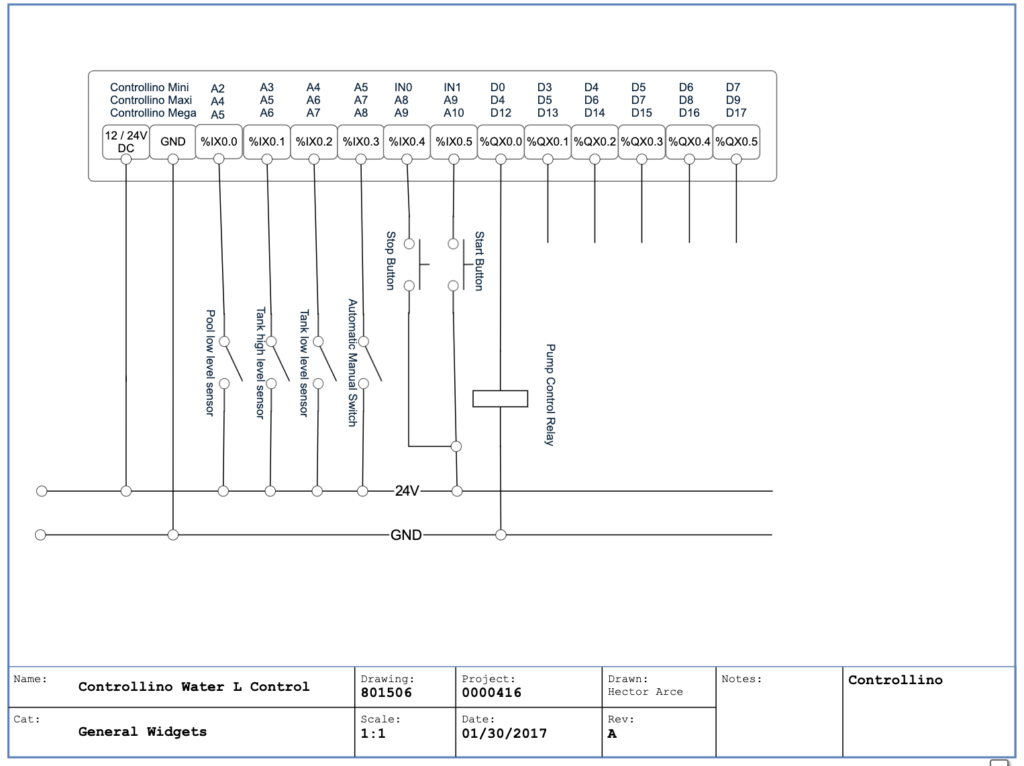
Automatic_Manual_Switch.
  • Press the Start Button to activate the pump and the Stop Button to deactivate it.

Ladder Logic Explanation

Automatic Mode

  1. Automatic Activation:
  • When both 
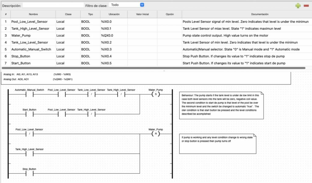
Pool_Low_Level_Sensor and Tank_Low_Level_Sensor are active, the pump (Water_Pump) turns on.
  1. Automatic Deactivation:
  • The pump turns off when either:
    • Tank_High_Level_Sensor is active (tank full).
    • Pool_Low_Level_Sensor is inactive (cistern empty).

Manual Mode

  1. Manual Control:
  • Pressing Start_Button turns on the pump manually.
  • Pressing Stop_Button turns off the pump manually.

Troubleshooting

  1. Check Wiring:
  • Ensure sensors and buttons are connected to the correct input pins.
  • Verify the pump is connected to the correct output pin.
  1. Verify Variables:
  • Check that the variable names in OpenPLC match the physical connections.
  1. Debugging:
  • Use the OpenPLC debugging tools to monitor the state of inputs, outputs, and signals.

Conclusion

Congratulations! You have successfully implemented a water reserve control system with both automatic and manual modes. This system is ideal for efficiently managing water levels in elevated tanks and cisterns. You can further customize the system by adding additional sensors or modifying the logic to suit specific requirements.

Share This Post

More Tutorials to explore

OpenPLC Editor for CONTROLLINO

Introduction In the world of industrial automation, having an intuitive and powerful programming environment is key. OpenPLC Editor, combined with CONTROLLINO, brings a seamless IEC