OpenPLC Editor for CONTROLLINO
Introduction In the world of industrial automation, having an intuitive and powerful programming environment is key. OpenPLC Editor, combined with CONTROLLINO, brings a seamless IEC
This is an example guide to setting up Modbus TCP communication between a client and server using CONTROLLINO and an Ethernet shield. This tutorial will help you configure the client to read and write inputs and outputs and the server to synchronize its state with the client.
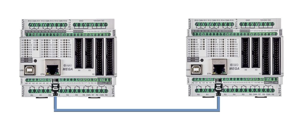
Point to point connection

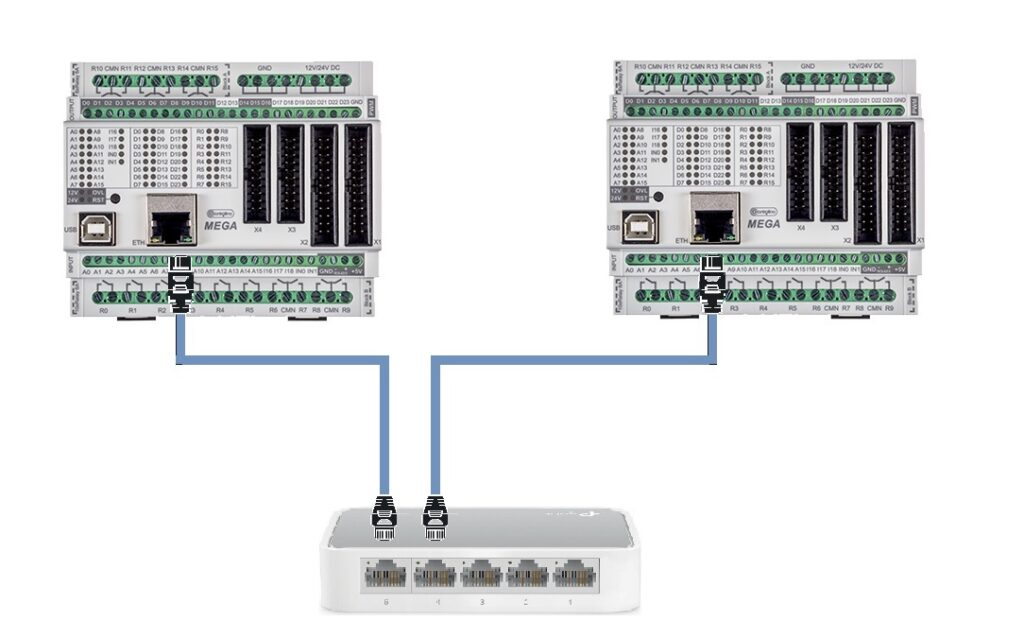
Connection using switch

You can download the example Modbus TCP Client and Server code from the following GitHub repository:
The Modbus TCP client communicates with the server to toggle coils and read and write registers.
Tools menu.ArduinoRS485ArduinoModbusControllinoSPIEthernetIn the setup() function:
Ethernet.begin(mac, ip) using the MAC address of your Ethernet shield.modbusTCPClient.begin(server, 502).In the loop() function:
slaveInputs[] to store the state of the slave’s digital inputs.modbusTCPClient.discreteInputRead().digitalWrite().modbusTCPClient.coilWrite().slaveInRegisters[] to store the state of the slave’s holding registers.modbusTCPClient.inputRegisterRead().analogWrite() and update the slave’s holding registers using modbusTCPClient.holdingRegisterWrite().The Modbus TCP server simulates a coil and synchronizes the state of its inputs and outputs with the client.
Tools menu.ArduinoRS485ArduinoModbusControllinoSPIEthernetIn the setup() function:
Ethernet.begin(mac, ip).modbusTCPServer.begin().modbusTCPServer.configureCoils()modbusTCPServer.configureDiscreteInputs()modbusTCPServer.configureHoldingRegisters()modbusTCPServer.configureInputRegisters()pinMode() to define the pins as either INPUT or OUTPUT.analogWrite().In the loop() function:
ethernetServer.available().modbusTCPServer.accept(client).executeSynchronization() function:
modbusTCPServer.coilRead(), and update the corresponding output pins using digitalWrite().digitalRead() and update the corresponding coil register with modbusTCPServer.coilWrite().analogWrite().modbusTCPServer.inputRegisterWrite().You have now successfully configured Modbus TCP communication between a CONTROLLINO client and server using an Ethernet shield. The client reads and writes digital and analog inputs/outputs, while the server synchronizes its state accordingly. Experiment with different pin configurations and data handling to expand your project!
Introduction In the world of industrial automation, having an intuitive and powerful programming environment is key. OpenPLC Editor, combined with CONTROLLINO, brings a seamless IEC
The project provides an easy to install tool to test the main features of the Controllino MICRO by serving an embedded web application directly from