Modbus RTU Master Slave I/O

Categories: , ,

Introduction

This tutorial will guide you through setting up Modbus RTU communication between a master and a slave device using two CONTROLLINO devices. The master device reads digital and analog inputs from the slave and sends data to control its outputs, while the slave responds with data controlling its own outputs based on commands received from the master.

Note

The Controllino BSP, for MAXI and MEGA, inside pins_arduino.h contains the following definitions:

// ArduinoRS485 library support
#define RS485_SERIAL_PORT Serial3
#define RS485_DEFAULT_TX_PIN 14
#define CUSTOM_RS485_DEFAULT_DE_PIN 75
#define CUSTOM_RS485_DEFAULT_RE_PIN 76

These allows the use of the default instance of RS485 library:

RS485Class RS485(RS485_SERIAL_PORT, RS485_DEFAULT_TX_PIN, RS485_DEFAULT_DE_PIN, RS485_DEFAULT_RE_PIN);

Which is also the default RS485 interface for ModbusRTUServer and ModbusRTUClient the default instances for RTU in ArduinoModbus library.

This allows an easy integration of the libraries and the Controllino BSP so there is not need to create an instance of RS485 and later an instance of ModbusRTUServer or ModbusRTUClient, but just use the default instances like in the library examples.
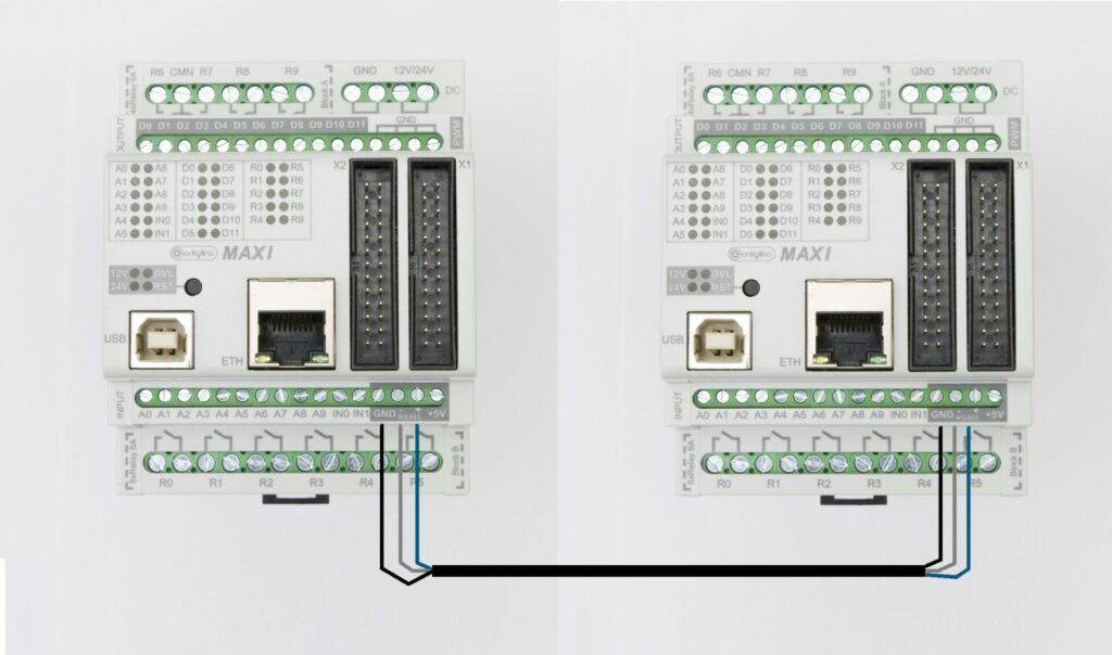
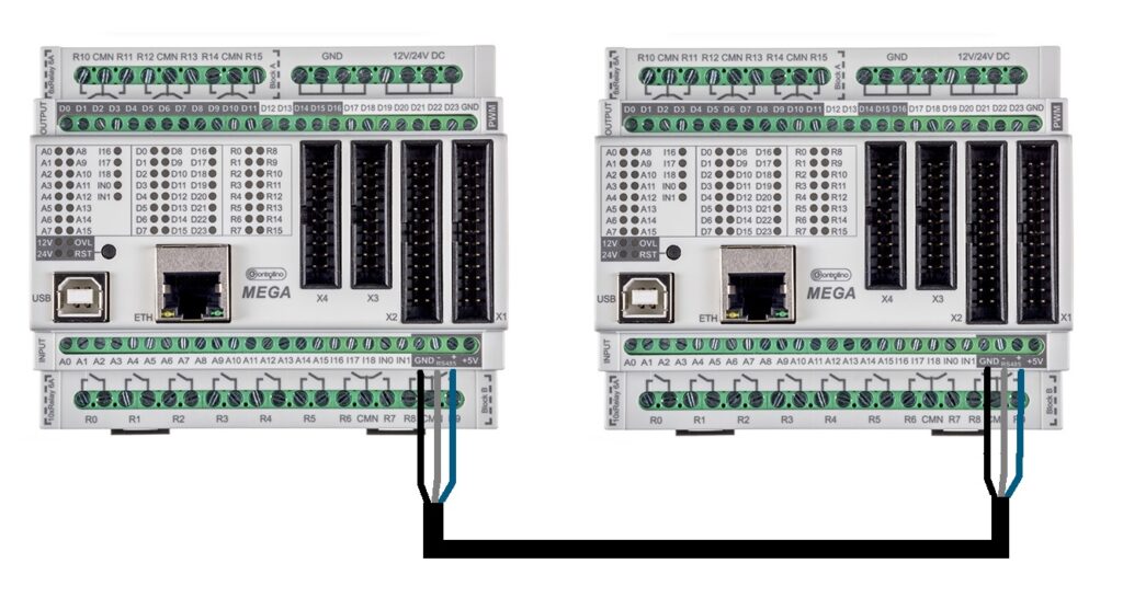
Prerequisites

  • Installed Arduino IDE.
  • CONTROLLINO Mega or Maxi PLC board for both master and slave devices.
  • Basic understanding of Modbus RTU communication and pin setup.

Example Code

You can download the example Modbus RTU master and slave code from the following GitHub repository:

  • Modbus RTU Master code
  • Modbus RTU Slave code
  • Detailed example explanation

Step-by-Step Guide

Step 1: Setup the Arduino Environment

  1. Connect your CONTROLLINO boards (both master and slave) to your computer.
  2. Open the Arduino IDE.
  3. Ensure the appropriate CONTROLLINO Mega board and port are selected in the Tools menu.
  4. Include the necessary libraries:
    • ArduinoRS485 library for Modbus RTU communication.
    • ArduinoModbus library for handling Modbus RTU protocol.
    • Controllino library to handle CONTROLLINO-specific pins.

Step 2: Initialize Modbus RTU Communication and Serial Debugging

  1. In the setup() function of both master and slave:
    • Initialize Modbus RTU communication by calling ModbusRTUClient.begin(9600) for the master and ModbusRTUServer.begin(1, 9600) for the slave. This sets up the master to communicate at a 9600 baud rate, and the slave is assigned ID 1.
    • Initialize serial communication for debugging purposes using Serial.begin(9600).
  2. On the master side, you will configure the Modbus client, while the slave initializes the Modbus server.

Step 3: Configure Digital and Analog Pins

  1. Master Configuration:
    • Digital Inputs and Outputs:
      • Configure digital pins CONTROLLINO_A0 to CONTROLLINO_A10 as inputs.
      • Configure relay pins CONTROLLINO_R0 to CONTROLLINO_R10 as outputs.
    • Analog Inputs and Outputs:
      • Configure analog input pins CONTROLLINO_A11 to CONTROLLINO_A15 as inputs.
      • Configure PWM output pins CONTROLLINO_D0 to CONTROLLINO_D4 as outputs.
  2. Slave Configuration:
    • Digital Inputs and Outputs:
      • The same digital input-output configuration will be applied to the slave.
    • Analog Inputs and Outputs:
      • Similarly, configure analog input pins and PWM output pins as on the master.

Step 4: Sending and Receiving Data Between Master and Slave

Master Code

In the loop() function:

  1. Start by reading the digital inputs (CONTROLLINO_A0 to CONTROLLINO_A10) on the master.
  2. Write the input states to the slave’s coils using ModbusRTUClient.coilWrite(). This will send the master’s inputs to the corresponding digital outputs (CONTROLLINO_R0 to CONTROLLINO_R10) on the slave.
  3. Read the analog input values on the master, and split the 10-bit values into Modbus registers. Write these to the slave’s holding registers.
  4. After sending data to the slave, read the slave’s discrete inputs and input registers to update the master’s digital and analog outputs.

Slave Code

In the loop() function of the slave:

  1. Use ModbusRTUServer.poll() to check for incoming Modbus requests from the master.
  2. For digital outputs, read the coil values sent by the master and update the digital output pins accordingly.
  3. For analog outputs, read the values from the holding registers and use them to set the PWM outputs.

Step 5: Synchronizing Digital and Analog Outputs

  1. The master’s digital outputs (CONTROLLINO_R0 to CONTROLLINO_R10) are updated based on the data received from the slave’s discrete inputs.
  2. The master’s analog outputs (CONTROLLINO_D0 to CONTROLLINO_D4) are updated based on the slave’s input registers.
  3. On the slave, the digital outputs and PWM outputs are controlled by the master’s Modbus write commands, allowing for synchronized control across the devices.

Step 6: Debugging and Monitoring Communication

  1. Add serial print statements to monitor Modbus communication between the master and slave.
  2. Ensure the Modbus client is correctly reading and writing data from and to the slave device.
  3. Use LEDs or external devices connected to the outputs to visualize changes in state as you control the system through Modbus communication.

Troubleshooting

  • Modbus Communication Issues: Verify the slave ID and Modbus address in both the master and slave codes.
  • Serial Debugging: Ensure the Serial Monitor is open at the correct baud rate (9600 baud).
  • Wiring: Double-check the RS485 connections between the master and slave devices. Ensure that the A+ and B-terminals are properly connected.
  • Pin Setup: Verify that the correct pins are configured as inputs and outputs on both the master and slave.

Conclusion

You have now successfully established Modbus RTU communication between a CONTROLLINO master and slave. The master reads digital and analog inputs, sends this data to the slave, and controls the slave’s outputs accordingly. Experiment with this setup to synchronize multiple devices or expand your project with additional sensors and actuators!

Also this tutorial can be a base example on how to extend the I/Os of a CONTROLLINO with another CONTROLLINO, using Modbus RTU and RS485.

Share This Post

More Tutorials to explore

Modbus TCP Master Client I/O

This is an example guide to setting up Modbus TCP communication between a client and server using CONTROLLINO and an Ethernet shield. This tutorial will

Modbus RTU Master Slave I/O

Introduction This tutorial will guide you through setting up Modbus RTU communication between a master and a slave device using two CONTROLLINO devices. The master device reads digital and analog inputs from the slave and sends