OpenPLC Editor for CONTROLLINO
Introduction In the world of industrial automation, having an intuitive and powerful programming environment is key. OpenPLC Editor, combined with CONTROLLINO, brings a seamless IEC
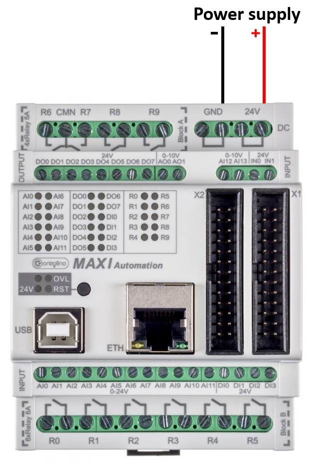
The MAXI Automation is the version of Controllino MAXI specifically tailored for the needs of automation specialists! It is the perfect compromise between compact size and big input and output number. The core competence is its flexibility.
In this example the usage of Controllino real analog (0-10V) outputs will be shown.
Controllino Maxi Automation has special:
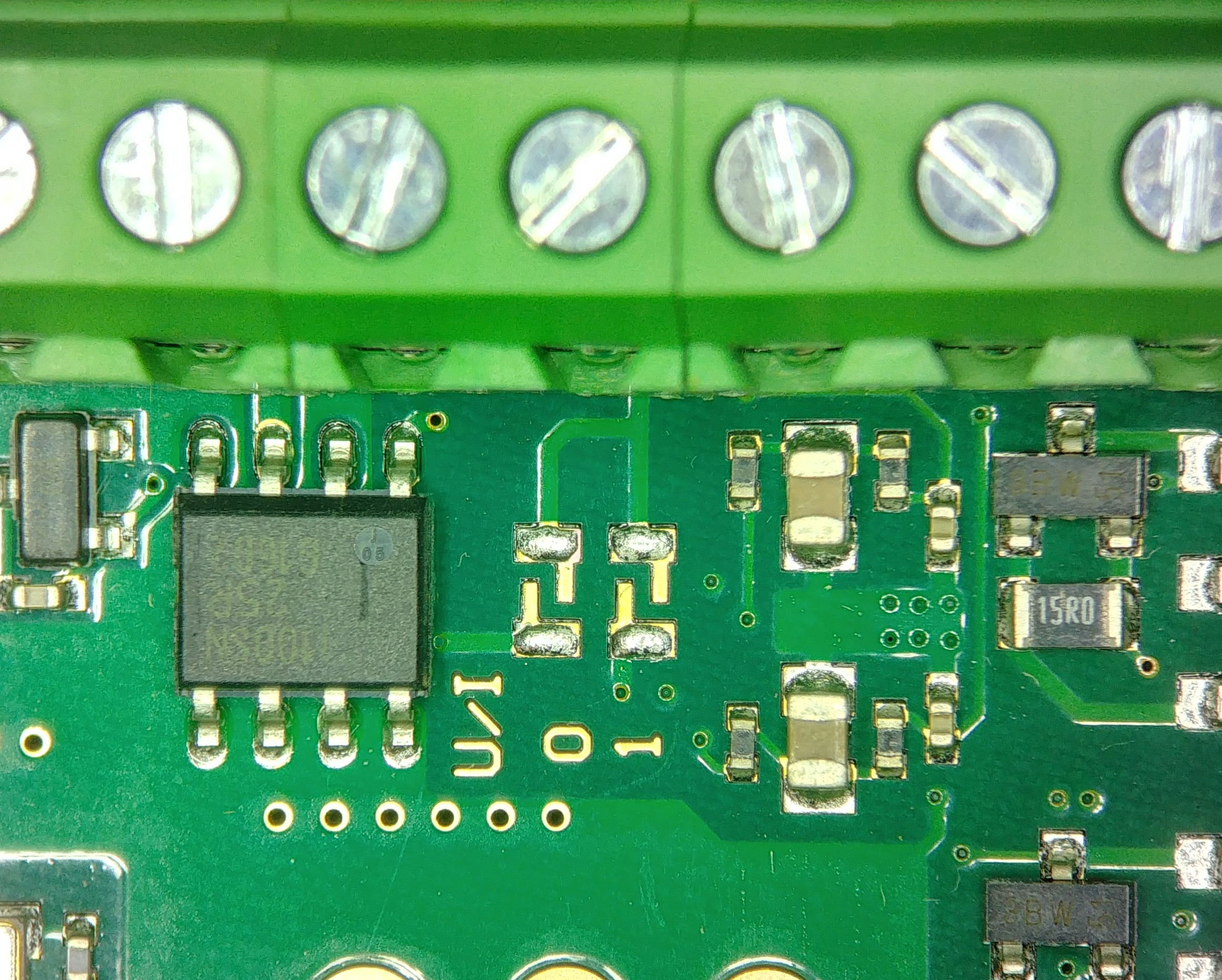
If you need two current (0-20mA), and not voltage (0-10V) outputs for your project, you can change them into current outputs by simply removing two 0 Ω resistors on Maxi Automation controll board. This process will be shown in next steps.
Note*
Pin header is working on 5V TTL levels. Voltage levels over 5.5V can damage the Controllino permanently.
To set your real analog outputs for your needs you can use the builtin example from Controllino Library, or you can copy the example from below.
#include <Controllino.h> /* Usage of CONTROLLINO library allows you to use CONTROLLINO_xx aliases in your sketch. */

// the setup function runs once when you press reset (CONTROLLINO RST button) or connect the CONTROLLINO to the PC
void setup() {
 // initialize all used digital output pins as outputs
 pinMode(CONTROLLINO_AO0, OUTPUT);
 pinMode(CONTROLLINO_AO1, OUTPUT);
}

// the loop function runs over and over again forever
void loop() {
 int analogOut0 = 127;                     // 0 - 255 to be set (0 - 10 000 mV, or 0 - 20 000 uA)
 int analogOut1 = 255;                     // 0 - 255 to be set (0 - 10 000 mV, or 0 - 20 000 uA)
 analogWrite(CONTROLLINO_AO0, analogOut0); // set the analog output 0 to 5V or 10mA
 analogWrite(CONTROLLINO_AO1, analogOut1); // set the analog output 1 to 10V or 20mA
}
If you are not able to compile the sketch, choose the Controllino MAXI Automation board!
To make the outputs and relays work, CONTROLLINO pins have to be set up as OUTPUTs!
pinMode(CONTROLLINO_xx, OUTPUT);In the following steps we will show you how to turn the voltage to the current outputs.
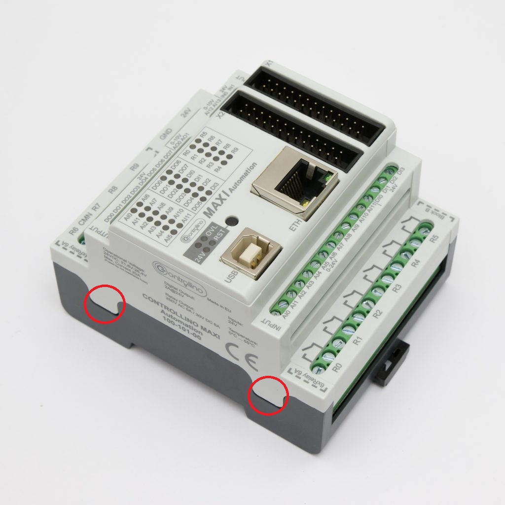
Remove the Controllino MAXI Automation cover by lifting marked sides of the cover with flat-head screwdriver:
Remove the plastic sides and disconnect the Controllino connection board
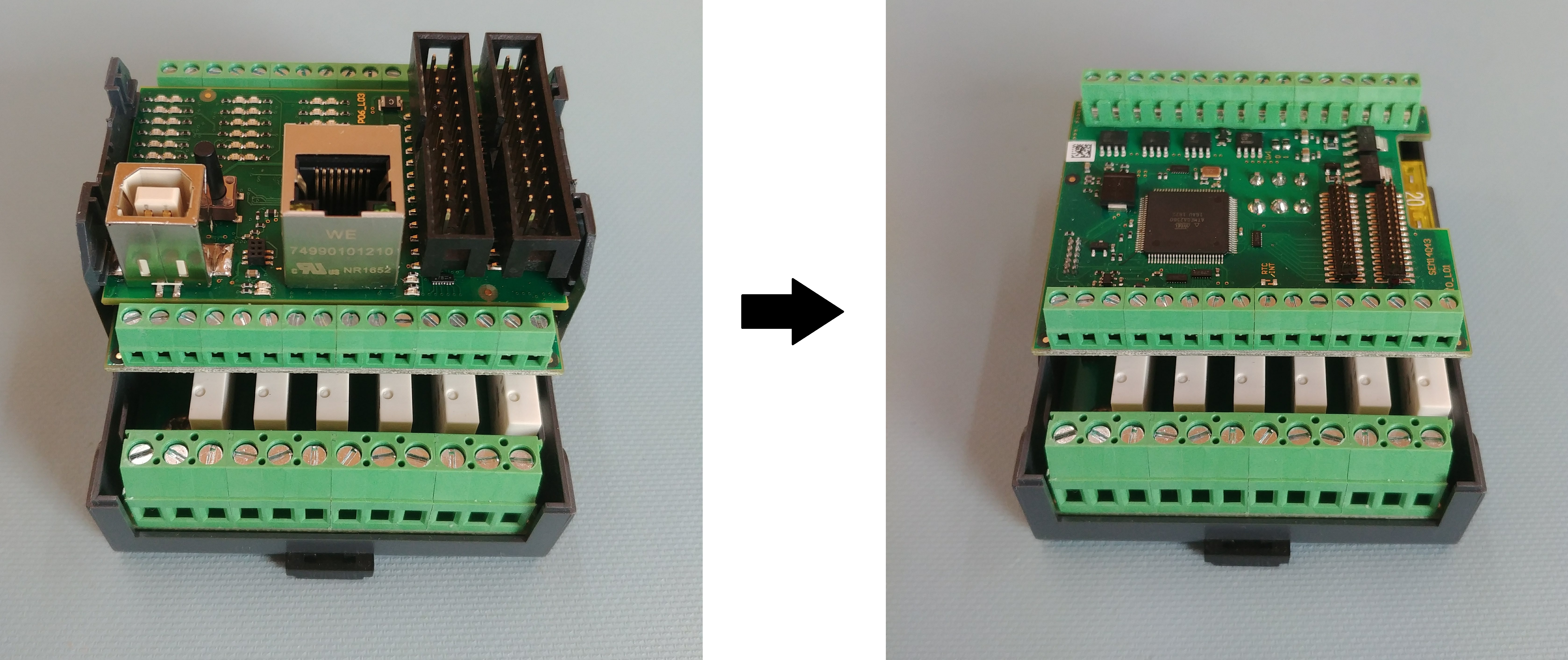
from the Controllino MAXI Automation.
Locate the two 0 Ω resistors of the Controllino relay board:
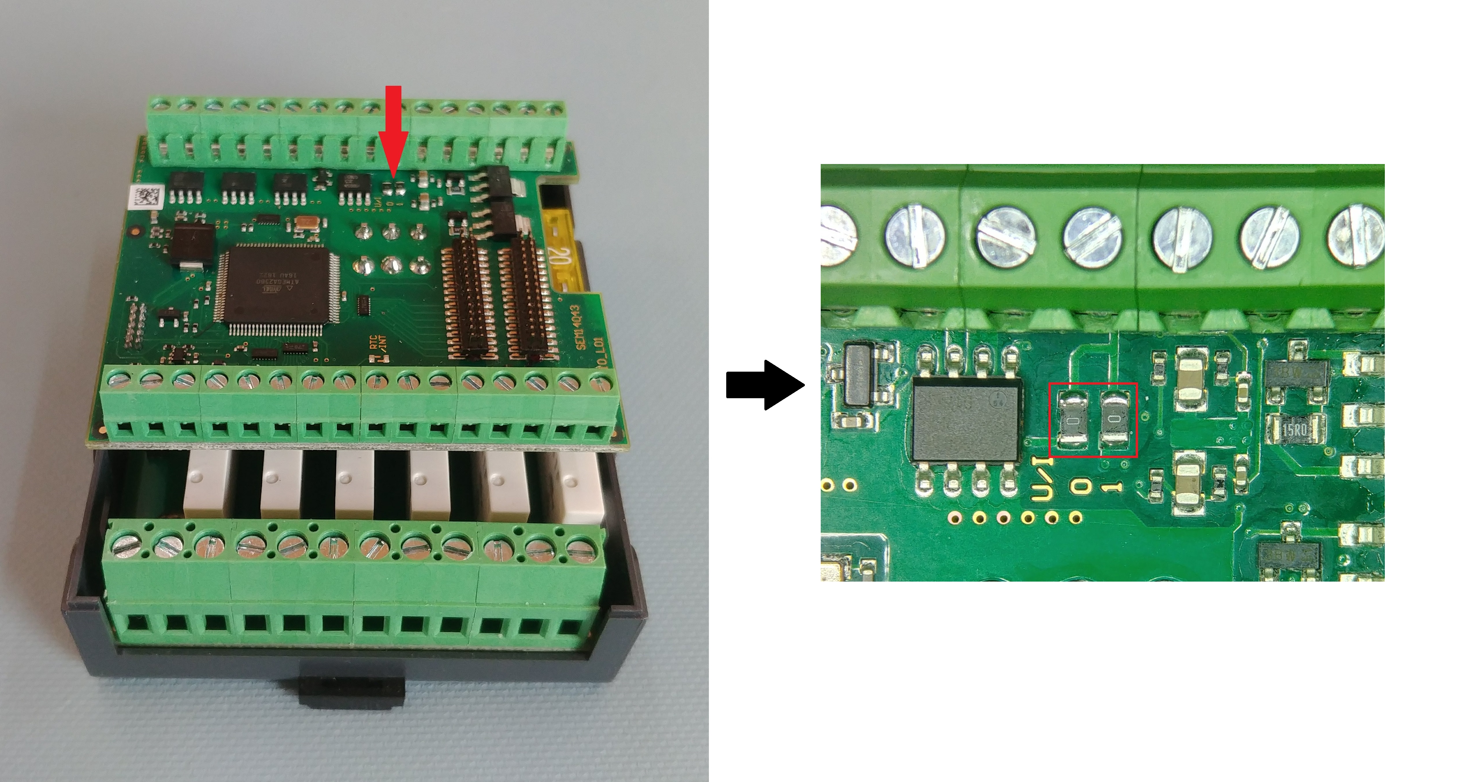
In order to get the two current outputs (0-20 mA) on Controllino MAXI Automation, apply heat and take the tweezers to remove two 0 Ω resistors:
To get back the voltage outputs (0-10V), simply solder the resistors back on Controllino MAXI Automation control board.
Note*
To test the outputs use previous example or example from the CONTROLLINO library for the Controllino MAXI Automation.
0-10 V -> 0-20 mA
If you are not able to compile the sketch, choose the Controllino MAXI Automation board!