OpenPLC Editor for CONTROLLINO
Introduction In the world of industrial automation, having an intuitive and powerful programming environment is key. OpenPLC Editor, combined with CONTROLLINO, brings a seamless IEC
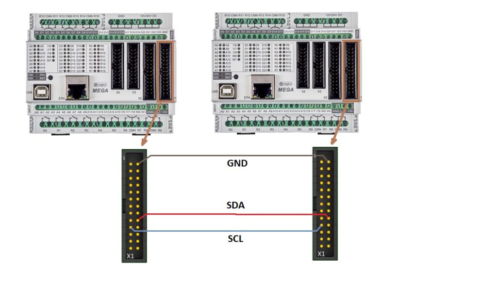
This tutorial will guide you through setting up I2C communication between a master and a slave device using a CONTROLLINO PLC. The master device reads analog and digital inputs and sends this data to the slave, while the slave responds with data that controls the outputs on the master.

This example of connection is based on the Controllino Mega but I2C connections for Maxi and Mini uses the same pins of the same X1 connector.
Please grab the following example .ino file from Github:
setup() function, initialize the I2C communication by calling Wire.begin(). This sets up the CONTROLLINO device as a master.Serial.begin(9600).CONTROLLINO_D0 to CONTROLLINO_D4) are configured as inputs.CONTROLLINO_R0 to CONTROLLINO_R4) are set as outputs.CONTROLLINO_A0 and CONTROLLINO_A1) are configured as inputs.loop() function, start communication with the slave by calling Wire.beginTransmission(slaveAddress).Wire.write().Wire.endTransmission(), request data from the slave by calling Wire.requestFrom(slaveAddress, 5).CONTROLLINO_R0 to CONTROLLINO_R4).digitalWrite() function is used to control these pins.Certainly! Here’s an expanded explanation with more details on how the slave code works and its interaction with the master:
In the slave code, the device is initialized with a specific I2C address using Wire.begin(8). This address must match the address used in the master code for communication to work.
The digital and analog pins on the slave are then configured:
This ensures that both the master and slave are working with the same configuration, which is essential for seamless data exchange.
The receiveEvent() function in the slave code is triggered whenever the master sends data to the slave. This function:
The slave then uses digitalWrite() to set its digital output pins based on the master’s instructions, allowing the master to control these outputs directly.
When the master requests data from the slave, the requestEvent() function on the slave is executed:
The slave then sends these values back to the master via Wire.write(), allowing the master to read the current state of the slave’s inputs and use this data in its control logic.
The master and slave continuously communicate over I2C to maintain synchronization:
This bidirectional data flow ensures the master can dynamically control and respond to the conditions on the slave, creating a cohesive system where both devices operate in harmony.
slaveAddress.You have now successfully established I2C communication between a CONTROLLINO master and slave. By reading analog and digital inputs on the master and controlling its outputs based on data received from the slave, this setup enables synchronized control between two devices. Experiment with different pin configurations and data handling to expand your project!
Introduction In the world of industrial automation, having an intuitive and powerful programming environment is key. OpenPLC Editor, combined with CONTROLLINO, brings a seamless IEC
The project provides an easy to install tool to test the main features of the Controllino MICRO by serving an embedded web application directly from