OpenPLC Editor for CONTROLLINO
Introduction In the world of industrial automation, having an intuitive and powerful programming environment is key. OpenPLC Editor, combined with CONTROLLINO, brings a seamless IEC
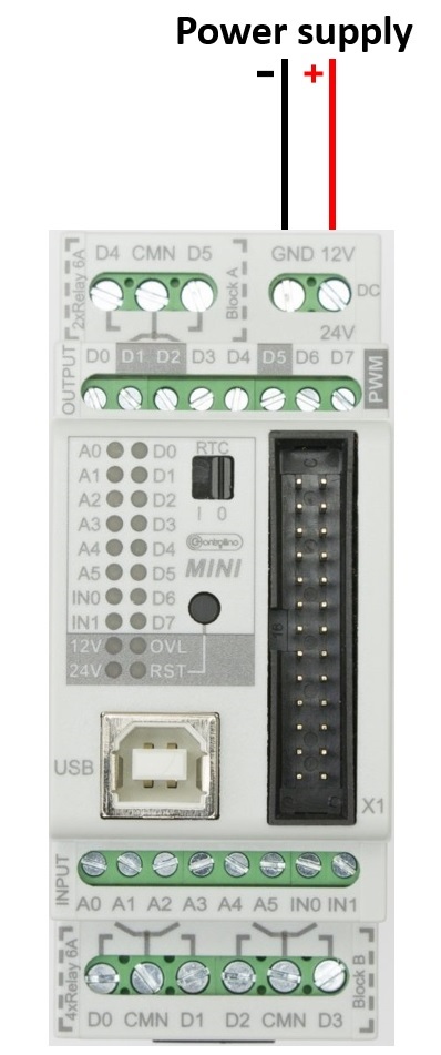
If you have a CONTROLLINO MINI device you can use the relay outputs “D0” to “D5” to connect and switch external circuits. The contact type as well as the contact connections are marked on the PLCs. The maximum permissible switching current per relay is 6A (at 250V / AC) or 6A (at a maximum of 30V / DC). The relay outputs are potential free!
On the CONTROLLINO MINI, the relays are connected parallelly to the digital outputs D0-D5 and thus are named D0-D5. If you switch the digital output, the relay digital output will also automatically be switched. In the case you don’t want that to happen you can disconnect the relay outputs by removing the solder line on the Controllino relay board.
Note*
Pin header is working on 5V TTL levels. Voltage levels over 5.5V can damage the Controllino permanently.
To check if your relay switches together with the digital output on your Controllino MINI, you can run this code for certain digital output.
#include <Controllino.h> /* Usage of CONTROLLINO library allows you to use CONTROLLINO_xx aliases in your sketch. */

// the setup function runs once when you press reset (CONTROLLINO RST button) or connect the CONTROLLINO to the PC
void setup() {
 // initialize all used digital output pins as outputs
 pinMode(CONTROLLINO_D0, OUTPUT);
}

// the loop function runs over and over again forever
void loop() {
 digitalWrite(CONTROLLINO_D0, HIGH); // turn the LED on (HIGH is the voltage level)
 delay(100);                         // wait for 100 milliseconds which is 1/10 of a second
 digitalWrite(CONTROLLINO_D0, LOW);  // turn the LED off by making the voltage LOW
 delay(100);                         // wait for 100 milliseconds which is 1/10 of a second
}
To make the outputs and relays blink, CONTROLLINO pins have to be set up as OUTPUTs!
pinMode(CONTROLLINO_xx, OUTPUT);In the following steps we will show you how to disconnect relays on the Controllino relay board.
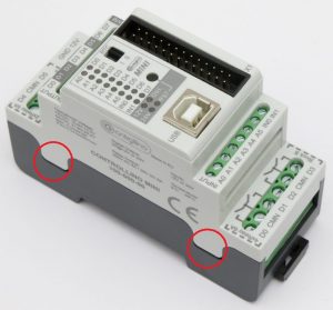
Remove the Controllino MINI cover by lifting marked sides of the cover with flat-head screwdriver:
Remove these two screws that hold Controllino relay board in place:
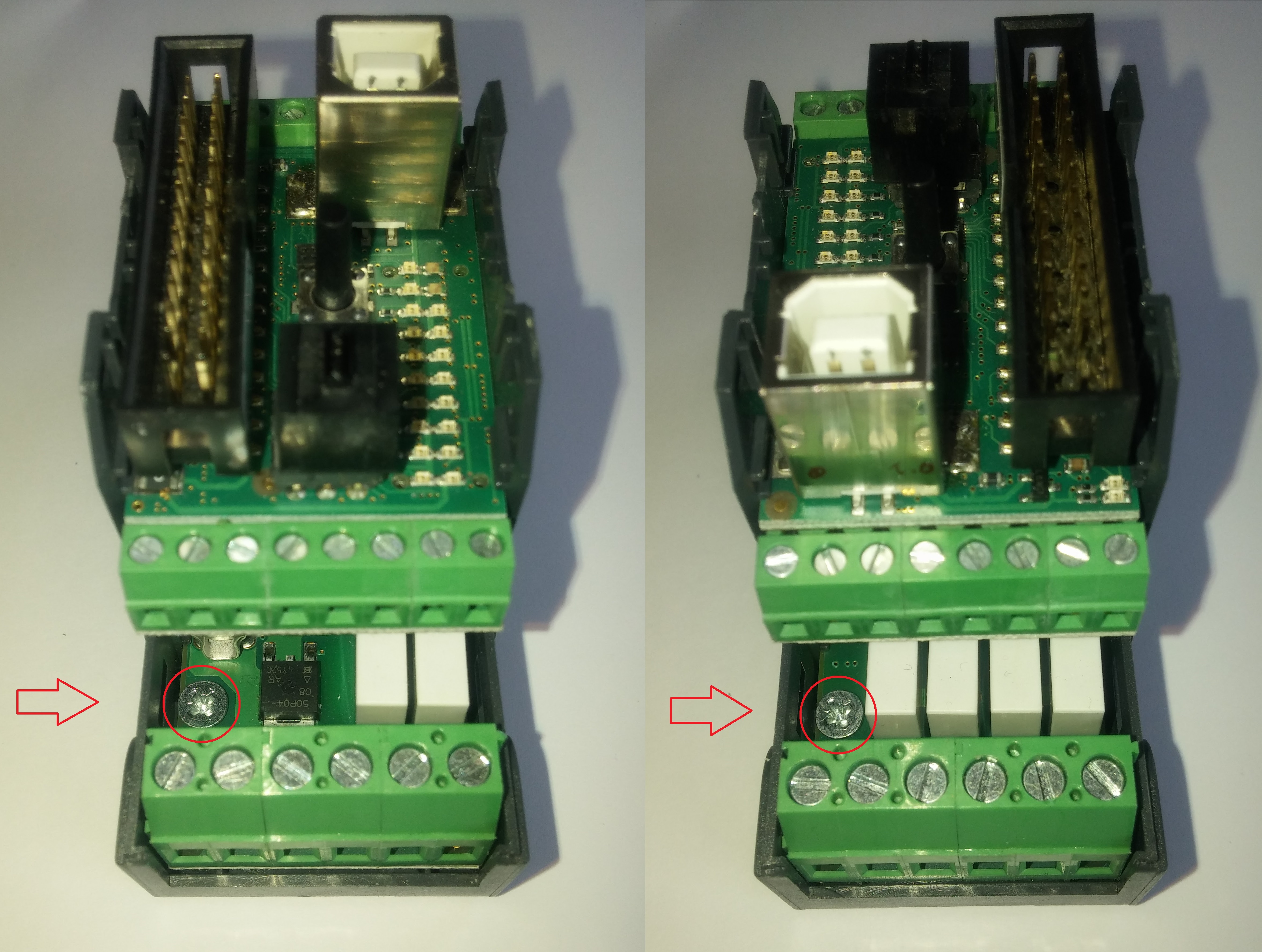
and separate the device from the bottom case.
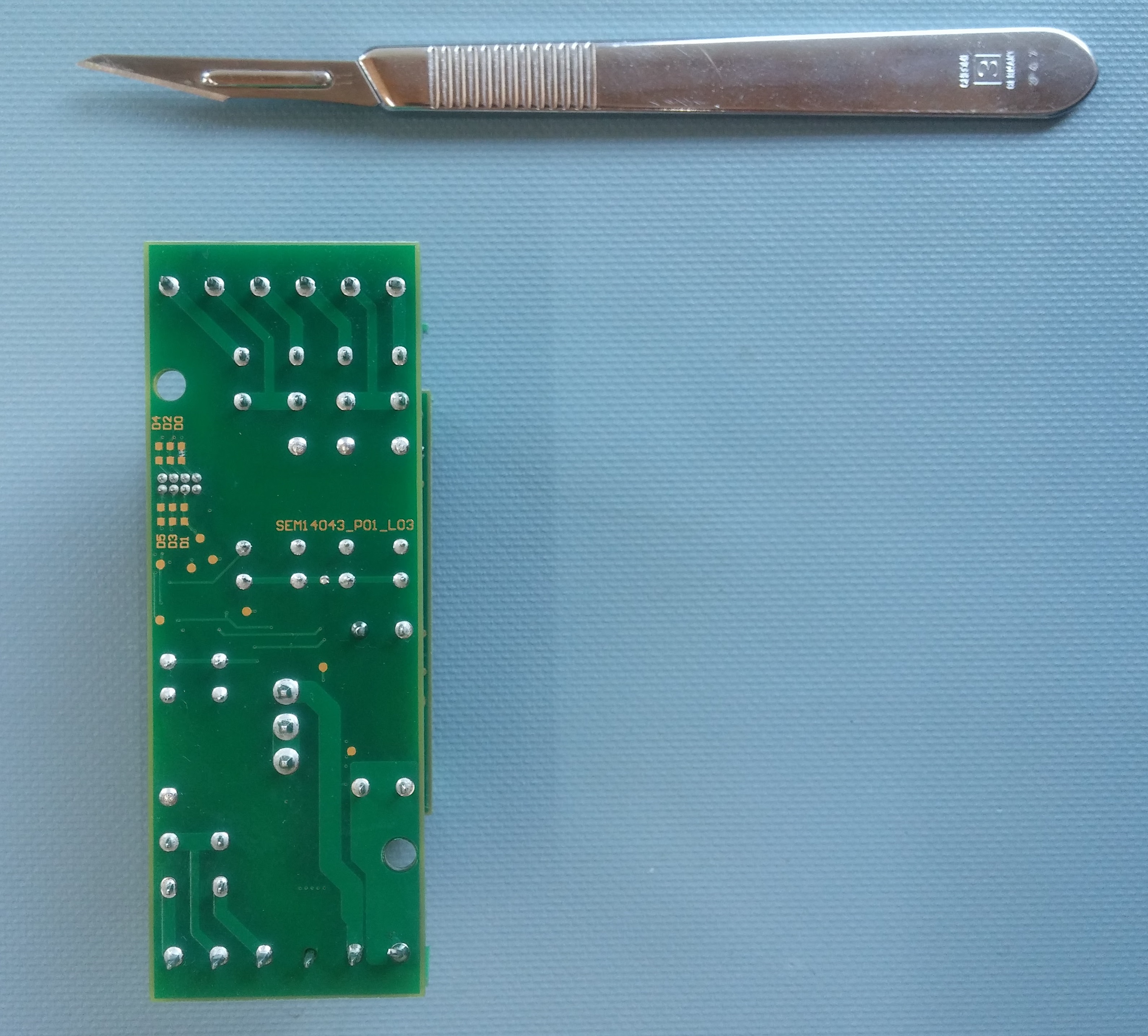
Turn to the bottom side of Controllino relay board:
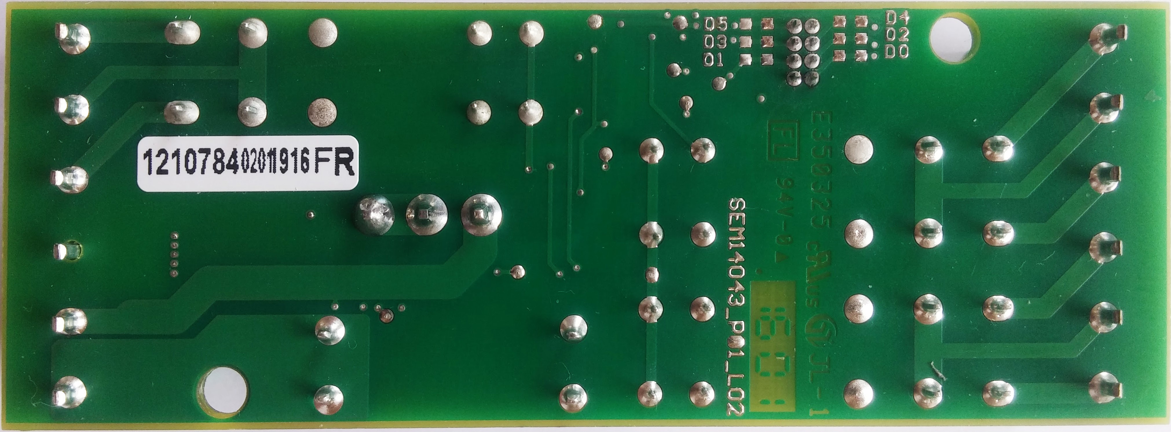
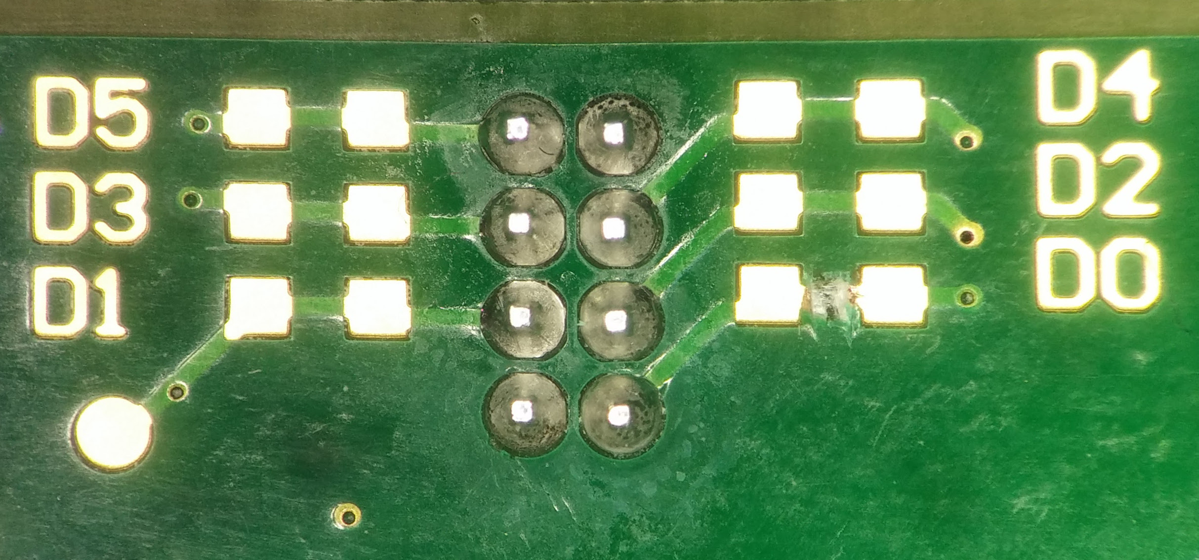
and locate this section on the right corner of the board:
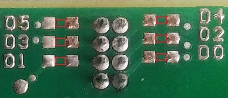
Take the sharp knife or scalpel and remove the solder line of the wanted digital output, marked with a red square on a previous picture. When removing the marked solder line, the best way is to make a cut on each side of the marked square and then remove the middle part.
In this example the relay D0 is disconnected from the digital output.
When you are finished you can upload the same program to check it again.
Note*
You can allways reconnect the relay outputs by connecting the 0 ohm smd resistor or some kind of conductor to reestablish the broken connection.