OpenPLC Editor for CONTROLLINO
Introduction In the world of industrial automation, having an intuitive and powerful programming environment is key. OpenPLC Editor, combined with CONTROLLINO, brings a seamless IEC
Information: In this tutorial we are using the HMI from Beijer.
Controllino HMIs are industrial HMI panels with high-resolution touch-screens and modern design. The panels combine IP65 corrosion resistant plastic housing with the full version of the iX software, providing an advanced HMI solution for every kind of applications.
Combine HMI with Controllino and you can create simple as well as the sophisticated applications in very short time.
IMPORTANT: Please, select proper target board in Tools->Board->Controllino MINI/MAXI/MEGA before Upload to your CONTROLLINO.
(Please, refer to https://github.com/CONTROLLINO-PLC/CONTROLLINO_Library if you do not see the CONTROLLINOs in the Arduino IDE menu Tools->Board.)
Note*
Pin header is working on 5V TTL levels. Voltage levels over 5.5V can damage the Controllino permanently.
To set up the Controllino HMI for communication and application we use the iX Software. iX Software is a revolutionary software that features drivers to communicate with your automation equipment, enhanced HMI functionality, state-of-the-art graphics, an intuitive design environment and a truly open platform for today’s automation market. iX Developer is a licensed application that runs on a Windows PC and is used to program iX operator panels.
Here we are going to show some steps on how to set it up properly. If you want to check more information and the iX user manual click here.
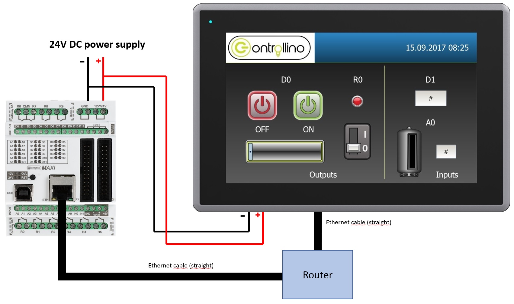
Download the Controllino HMI – TCP/IP example and run it in the iX software.
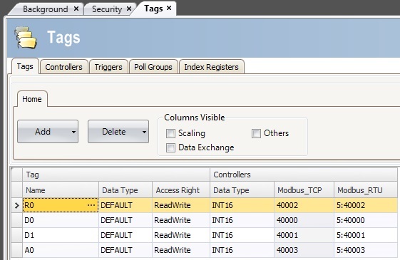
From the left side of the main screen in the iX example there is the Tags button. Open the Tags to set your application addresses. You can see example of this on the next picture:
For more information about Tags and addressing of them navigate to Controllers/Settings and click on the help button of the Modbus Master controller.
After that go to the Controllers tab to choose the right controller for communication. When we are using the Controllino device we want to choose MODICON -> Modbus Master controller. In this example it is already done and they are named Modbus_TCP and Modbus_RTU.
Press on the Modbus_TCP controller, activate it and click on the Settings button to do the folowing:
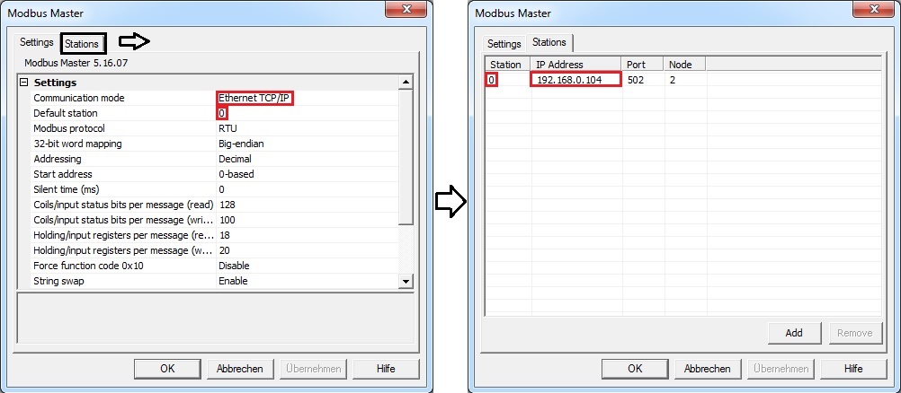
Set communication mode to the Ethernet TCP/IP and the IP address of the station to your Controllino IP address. To get your Controllino IP address and to ensure that the connections work, run the ArduinoIDE->File->Examples->Ethernet->DhcpAddressPrinter example, upload it and open Serial Monitor. If everything works, you should get your IP address on the screen.
Before uploading the program to the Controllino you have to install the Modbus TCP library. You can download it here. To install it copy the Modbus folder to your Arduino->libraries folder.
After getting the IP address of the Controllino the new program has to be uploaded to the device.
#include <Controllino.h>
#include <SPI.h>
#include <Ethernet.h>

#include "Mudbus.h"

Mudbus Mb;

int D0 = CONTROLLINO_D0;
int D1 = CONTROLLINO_D1;
int R0 = CONTROLLINO_R0;
int A0_ = CONTROLLINO_A0;


//Function codes 1(read coils), 3(read registers), 5(write coil), 6(write register)
//signed int Mb.R[0 to 125] and bool Mb.C[0 to 128] MB_N_R MB_N_C
//Port 502 (defined in Mudbus.h) MB_PORT

void setup()
{
 uint8_t mac[] = { 0x00, 0xAA, 0xBB, 0xCC, 0xDE, 0x02 };
 uint8_t ip[] = { 192, 168, 0, 103 }; // CHANGE this to the IP address of your CONTROLLINO
 uint8_t gateway[] = { 192, 168, 0, 254 };
 uint8_t subnet[] = { 255, 255, 255, 0 };
 Ethernet.begin(mac, ip, gateway, subnet);

 delay(5000);
 Serial.begin(9600);
 Serial.println("Started");

 pinMode(D0, OUTPUT);
 pinMode(D1, INPUT);
 pinMode(R0, OUTPUT);
 pinMode(A0_, INPUT);
}

void loop()
{

 Mb.Run();

 analogWrite(D0, Mb.R[0]);
 digitalWrite(R0, Mb.R[2]);
 Mb.R[1] = digitalRead(D1);
 Mb.R[3] = analogRead(A0_);

}
Note*
Pin header is working on 5V TTL levels. Voltage levels over 5.5V can damage the Controllino permanently.
To set up the Controllino HMI for communication and application we use the iX Software. iX Software is a revolutionary software that features drivers to communicate with your automation equipment, enhanced HMI functionality, state-of-the-art graphics, an intuitive design environment and a truly open platform for today’s automation market. iX Developer is a licensed application that runs on a Windows PC and is used to program iX operator panels.
Here we are going to show some steps on how to set it up properly. If you want to check more information and the iX user manual click here.
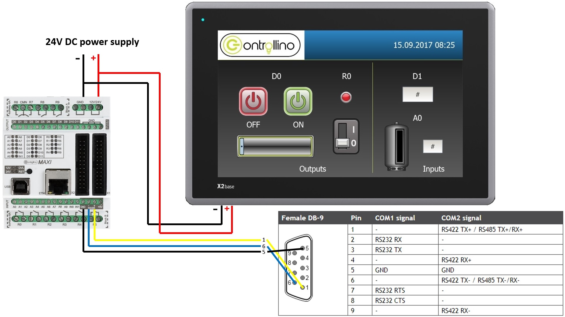
Download the Controllino HMI – RTU example and run it in the iX software.
From the left side of the main screen in the iX example there is the Tags button. Open the Tags to set your application addresses. You can see example of this on the next picture:
For more information about Tags and addressing of them navigate to Controllers/Settings and click on the help button of the Modbus Master controller.
Notice here that the Modbus_RTU tags are starting with “5:”. For communication with other stations than the default station, the station number is given as a prefix to the device. This is stated either as a fixed number or as an index register between I1 and I8. The station number is referring to a specific unit id. (5:40001 addresses holding register 40001 in station 5.) In our case the Controllino is slave device on station 5. We can always define his station in the code that we upload.
After that go to the Controllers tab to choose the right controller for communication. When we are using the Controllino device we want to choose MODICON -> Modbus Master controller. In this example it is already done and they are named Modbus_TCP and Modbus_RTU.
Press on the Modbus_RTU controller, activate it and click on the Settings button to do the folowing steps:
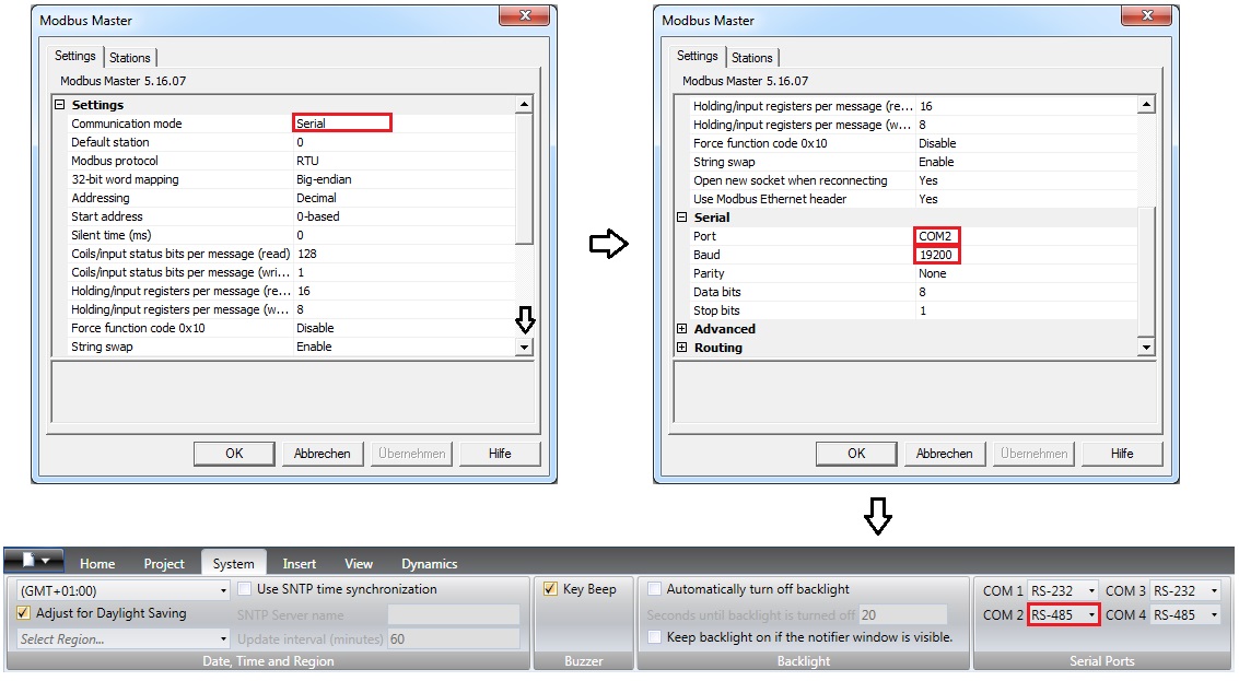
Set communication mode to the Serial and the COM2 port of your Controllino HMI. Don’t forget to match the baud rate of Controllino and HMI. Choose the COM2 port to be RS-485.
The Controllino HMI is communicating to the Controllino slave device on the station 5 so we have to set it in the line: define SlaveModbusAdd 5
#include <Controllino.h> /* Usage of CONTROLLINO library allows you to use CONTROLLINO_xx aliases in your sketch. */
#include "ModbusRtu.h" /* Usage of ModBusRtu library allows you to implement the Modbus RTU protocol in your sketch. */
/*
 CONTROLLINO - Modbus RTU protocol Slave example for MAXI and MEGA, Version 01.00

 The sketch is relevant only for CONTROLLINO variants MAXI and MEGA (because of necessity of RS485 interface)!

 This sketch is intended as an example of the communication between devices via RS485 with utilization the
 ModbusRTU protocol.
 In this example the CONTROLLINO is used as the Modbus slave!
 For more information about the Modbus protocol visit the website: https://modbus.org/

 Modbus master device can read Modbus 16bit registers (provided by the slave):
 0 - analog CONTROLLINO_A0 value (0 - 1024)
 1 - digital CONTROLLINO_D0 value (0/1)
 2 - Modbus messages received
 3 - Modbus messages transmitted

 Modbus master device can write Modbus 16bit registers:
 4 - relay CONTROLLINO_R0 (0/1)
 5 - relay CONTROLLINO_R1 (0/1)
 6 - relay CONTROLLINO_R2 (0/1)
 7 - relay CONTROLLINO_R3 (0/1)

 To easily evaluate this example you need a second CONTROLLINO as Modbus master running DemoModbusRTUMaster
 example sketch.
 Please note that both CONTROLLINOs need 12/24V external supply and you need to interconnect GND, -, + signals
 of RS485 screw terminal.

 Modbus Master-Slave library for Arduino (ModbusRtu.h) was taken from the website:
 https://github.com/smarmengol/Modbus-Master-Slave-for-Arduino
 It was necessary to modify setting of the PORTJ for pins DE and RE control. These pins are located at the
 PORJ and on the pins PIN6(DE) and PIN5(RE).

 IMPORTANT INFORMATION!
 Please, select proper target board in Tools->Board->Controllino MAXI/MEGA before Upload to your CONTROLLINO.
 (Please, refer to https://github.com/CONTROLLINO-PLC/CONTROLLINO_Library if you do not see the CONTROLLINOs in
 the Arduino IDE menu Tools->Board.)

 Created 30 March 2017
 by David


 (Check https://github.com/CONTROLLINO-PLC/CONTROLLINO_Library for the latest CONTROLLINO related software stuff.)
*/
int D0 = CONTROLLINO_D0;
int D1 = CONTROLLINO_D1;
int R0 = CONTROLLINO_R0;
int A0_ = CONTROLLINO_A0;

// This MACRO defines Modbus slave address.
// For any Modbus slave devices are reserved addresses in the range from 1 to 247.
// Important note only address 0 is reserved for a Modbus master device!

#define SlaveModbusAdd 5

// This MACRO defines number of the comport that is used for RS 485 interface.
// For MAXI and MEGA RS485 is reserved UART Serial3.

#define RS485Serial 3

// The object ControllinoModbuSlave of the class Modbus is initialized with three parameters.
// The first parametr specifies the address of the Modbus slave device.
// The second parameter specifies type of the interface used for communication between devices - in this sketch
// is used RS485.
// The third parameter can be any number. During the initialization of the object this parameter has no effect.

Modbus ControllinoModbusSlave(SlaveModbusAdd, RS485Serial, 0);

// This uint16 array specified internal registers in the Modbus slave device.
// Each Modbus device has particular internal registers that are available for the Modbus master.
// In this example sketch internal registers are defined as follows:
// (ModbusSlaveRegisters 0 - 3 read only and ModbusSlaveRegisters 4 - 7 write only from the Master perspective):
// ModbusSlaveRegisters[0] - Read an analog value from the CONTROLLINO_A0 - returns value in the range from 0 to 1023.
// ModbusSlaveRegisters[1] - Read an digital value from the CONTROLLINO_D0 - returns only the value 0 or 1.
// ModbusSlaveRegisters[2] - Read the number of incoming messages - Communication diagnostic.
// ModbusSlaveRegisters[3] - Read the number of number of outcoming messages - Communication diagnostic.
// ModbusSlaveRegisters[4] - Sets the Relay output CONTROLLINO_R0 - only the value 0 or 1 is accepted.
// ModbusSlaveRegisters[5] - Sets the Relay output CONTROLLINO_R1 - only the value 0 or 1 is accepted.
// ModbusSlaveRegisters[6] - Sets the Relay output CONTROLLINO_R2 - only the value 0 or 1 is accepted.
// ModbusSlaveRegisters[7] - Sets the Relay output CONTROLLINO_R3 - only the value 0 or 1 is accepted.

uint16_t ModbusSlaveRegisters[8];

// The setup function runs once when you press reset (CONTROLLINO RST button) or connect the CONTROLLINO to the PC
// In the setup function is carried out port setting and initialization of communication of the Modbus slave protocol.

void setup()
{
 delay(5000);
 Serial.begin(9600);
 Serial.println("Started");

 pinMode(D0, OUTPUT);
 pinMode(D1, INPUT);
 pinMode(R0, OUTPUT);
 pinMode(A0_, INPUT);

 ControllinoModbusSlave.begin( 19200 ); // Start the communication over the ModbusRTU protocol. Baund rate is set at 19200.
 Serial.begin(9600);

}

// The loop function runs over and over again forever
void loop()
{
 // This instance of the class Modbus checks if there are any incoming data.
 // If any frame was received. This instance checks if a received frame is Ok.
 // If the received frame is Ok the instance poll writes or reads corresponding values to the internal registers
 // (ModbusSlaveRegisters).
 // Main parameters of the instance poll are address of the internal registers and number of internal registers.

 ControllinoModbusSlave.poll(ModbusSlaveRegisters, 8);

 // While are not received or sent any data, the Modbus slave device periodically reads the values of analog and
 // digital outputs.
 // Also it updates the other values of registers.

 analogWrite(D0, ModbusSlaveRegisters[0]);
 digitalWrite(R0, ModbusSlaveRegisters[2]);
 ModbusSlaveRegisters[1] = digitalRead(D1);
 ModbusSlaveRegisters[3] = analogRead(A0_);

}