OpenPLC Editor for CONTROLLINO
Introduction In the world of industrial automation, having an intuitive and powerful programming environment is key. OpenPLC Editor, combined with CONTROLLINO, brings a seamless IEC
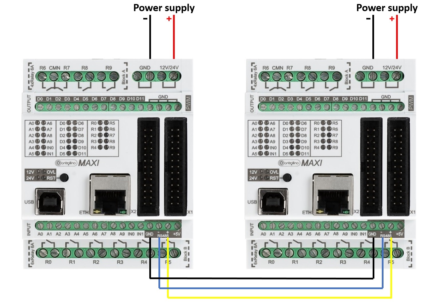
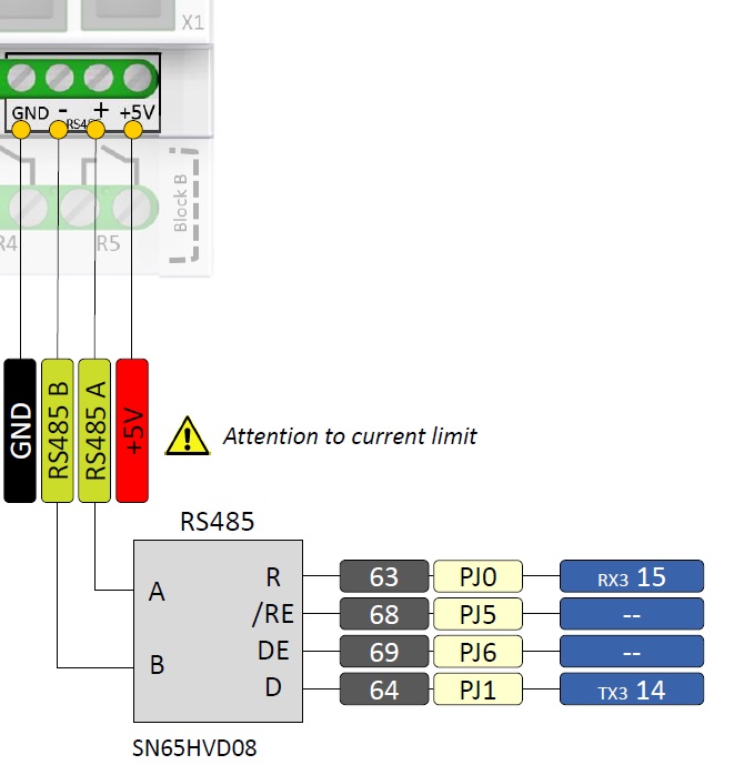
The CONTROLLINO PLCs MAXI and MEGA have an RS485 interface type SN65HVD08, which allows it to communicate with other RS485 devices. The RS485 is an interface-standard for digital, line-connected and differential serial data transmission. Connection to the interface is possible via screw terminals. It can carry signals up to about 1.200 metres with 32 subscribers. There is a large number of different components on the market that have an RS485 interface – they can communicate with the CONTROLLINO PLCs.
The RS485 driver module is connected to the UART3 (TxD3 / RxD3) of the ATMEGA2560.
IMPORTANT INFORMATION!
You can download a “PINOUT-table” for MAXI here. In these files, you can easily see all internal wiring indications between clamps and the microcontroller.
Please, select proper target board in Tools->Board->Controllino MINI/MAXI/MEGA before Upload to your CONTROLLINO.
(Please, refer to https://github.com/CONTROLLINO-PLC/CONTROLLINO_Library if you do not see the CONTROLLINOs in the Arduino IDE menu Tools->Board.)
Note*
Pin header is working on 5V TTL levels. Voltage levels over 5.5V can damage the Controllino permanently.
This example code is for testing your RS485 interface. Upload first code on CONTROLLINO sending device and the second code on CONTROLLINO receiving device. After programming them, connect the Controllinos according to the previous picture and turn on Serial Monitor on receiving Controllino.
#include <SPI.h>
#include <Controllino.h> /* Usage of CONTROLLINO library allows you to use CONTROLLINO_xx aliases in your sketch. */

void TestRS485 (int mode)
{
 DDRJ = DDRJ | B01100000;
 PORTJ = PORTJ & B10011111;
 /*pinMode(CONTROLLINO_RS485_TX, OUTPUT);
 pinMode(CONTROLLINO_RS485_RX, INPUT);
 pinMode(CONTROLLINO_RS485_RE, OUTPUT);
 pinMode(CONTROLLINO_RS485_DE, OUTPUT);*/
 switch (mode)
 {
 case 0:
 PORTJ = PORTJ & B10011111;
 PORTJ = PORTJ | B01000000;
 /*digitalWrite (CONTROLLINO_RS485_RE, HIGH);
 digitalWrite (CONTROLLINO_RS485_DE, HIGH);*/
 delay (10);
 Serial.println ("Sending test message, expected to return;");
 Serial3.print("UUUUU Controllino RS485 test Message.UUUUU");
 break;

 case 1:
 PORTJ = PORTJ & B10011111;
 PORTJ = PORTJ | B01100000;
 /*digitalWrite (CONTROLLINO_RS485_RE, LOW);
 digitalWrite (CONTROLLINO_RS485_DE, HIGH);*/
 delay (10);
 Serial.println ("Sending test message, not expected to return;");
 Serial3.print("UUUUU Controllino RS485 test Message.UUUUU");
 break;

 case 2:
 PORTJ = PORTJ & B10011111;
 PORTJ = PORTJ | B00100000;
 /* digitalWrite (CONTROLLINO_RS485_RE, HIGH);
 digitalWrite (CONTROLLINO_RS485_DE, LOW);*/
 delay (10);
 Serial.println ("Sending test message, not expected to be sended;");
 Serial3.print("UUUUU Controllino RS485 test Message.UUUUU");
 break;

 default:
 Serial.println("Wrong mode!");
 return;
 }
}

/* This function enters loop and waits for any incoming data on serial 3.*/
void RecieveRS485()
{
 Serial.println("Recieving RS485.");
 while(true)
 {
 if (Serial3.available())
 {
 // print the new byte:
 Serial.print((char)Serial3.read());
 }
 }
}

void setup() {
 /* Here we initialize USB serial at 9600 baudrate for reporting */
 Serial.begin(9600);
 /* Here we initialize RS485 serial at 9600 baudrate for communication */
 Serial3.begin(9600);
 /* This will initialize Controllino RS485 pins */
 Controllino_RS485Init();

}

void loop() {
 /* Use only one of the two functions, either send or recieve */
 // RecieveRS485();

 /* Send test. 2 seconds apart sending messages with 3 types of different settings.
    Check the function comment for more infromation */
 TestRS485(0);
 delay(2000);
 TestRS485(1);
 delay(2000);
 TestRS485(2);
 delay(2000);

}#include <SPI.h>
#include <Controllino.h> /* Usage of CONTROLLINO library allows you to use CONTROLLINO_xx aliases in your sketch. */
void TestRS485 (int mode)
{
DDRJ = DDRJ | B01100000;
PORTJ = PORTJ & B10011111;
/*pinMode(CONTROLLINO_RS485_TX, OUTPUT);
pinMode(CONTROLLINO_RS485_RX, INPUT);
pinMode(CONTROLLINO_RS485_RE, OUTPUT);
pinMode(CONTROLLINO_RS485_DE, OUTPUT);*/
switch (mode)
{
case 0:
PORTJ = PORTJ & B10011111;
PORTJ = PORTJ | B01000000;
/*digitalWrite (CONTROLLINO_RS485_RE, HIGH);
digitalWrite (CONTROLLINO_RS485_DE, HIGH);*/
delay (10);
Serial.println ("Sending test message, expected to return;");
Serial3.print("UUUUU Controllino RS485 test Message.UUUUU");
break;
case 1:
PORTJ = PORTJ & B10011111;
PORTJ = PORTJ | B01100000;
/*digitalWrite (CONTROLLINO_RS485_RE, LOW);
digitalWrite (CONTROLLINO_RS485_DE, HIGH);*/
delay (10);
Serial.println ("Sending test message, not expected to return;");
Serial3.print("UUUUU Controllino RS485 test Message.UUUUU");
break;
case 2:
PORTJ = PORTJ & B10011111;
PORTJ = PORTJ | B00100000;
/* digitalWrite (CONTROLLINO_RS485_RE, HIGH);
digitalWrite (CONTROLLINO_RS485_DE, LOW);*/
delay (10);
Serial.println ("Sending test message, not expected to be sended;");
Serial3.print("UUUUU Controllino RS485 test Message.UUUUU");
break;
default:
Serial.println("Wrong mode!");
return;
}
}
/* This function enters loop and waits for any incoming data on serial 3.*/
void RecieveRS485()
{
Serial.println("Recieving RS485.");
while(true)
{
if (Serial3.available())
{
// print the new byte:
Serial.print((char)Serial3.read());
}
}
}
void setup() {
/* Here we initialize USB serial at 9600 baudrate for reporting */
Serial.begin(9600);
/* Here we initialize RS485 serial at 9600 baudrate for communication */
Serial3.begin(9600);
/* This will initialize Controllino RS485 pins */
Controllino_RS485Init();
}
void loop() {
/* Use only one of the two functions, either send or recieve */
RecieveRS485();
/* Send test. 2 seconds apart sending messages with 3 types of different settings.
Check the function comment for more infromation */
// TestRS485(0);
// delay(2000);
// TestRS485(1);
// delay(2000);
// TestRS485(2);
// delay(2000);
}After successful test of your CONTROLLINOs you can proceed with communication between devices via RS485 with utilization the ModbusRTU protocol. In this example the CONTROLLINOs are used as the Modbus master and slave!
For more information about the Modbus protocol visit the website: https://modbus.org/
The sketch is relevant only for CONTROLLINO variants MAXI and MEGA (because of necessity of RS485 interface)!
Modbus master device periodically reads Modbus 16bit registers (provided by the slave) and prints the current state to the debug Serial:
0 – analog CONTROLLINO_A0 value (0 – 1024)
1 – digital CONTROLLINO_D0 value (0/1)
2 – Modbus messages received
3 – Modbus messages transmitted
Modbus master device periodically writes and toggles Modbus 16bit registers:
4 – relay CONTROLLINO_R0 (0/1)
5 – relay CONTROLLINO_R1 (0/1)
6 – relay CONTROLLINO_R2 (0/1)
7 – relay CONTROLLINO_R3 (0/1)
To easily evaluate this example you need a second CONTROLLINO as Modbus slave running DemoModbusRTUSlave example sketch.
Modbus Master-Slave library for Arduino (ModbusRtu.h) was taken from the website: https://github.com/smarmengol/Modbus-Master-Slave-for-Arduino
It was necessary to modify setting of the PORTJ for pins DE and RE control. These pins are located at the PORTJ and on the pins PIN6(DE) and PIN5(RE).
#include <Controllino.h> /* Usage of CONTROLLINO library allows you to use CONTROLLINO_xx aliases in your sketch. */
#include "ModbusRtu.h" /* Usage of ModBusRtu library allows you to implement the Modbus RTU protocol in your sketch. */

// This MACRO defines Modbus master address.
// For any Modbus slave devices are reserved addresses in the range from 1 to 247.
// Important note only address 0 is reserved for a Modbus master device!

#define MasterModbusAdd 0
#define SlaveModbusAdd 1

// This MACRO defines number of the comport that is used for RS 485 interface.
// For MAXI and MEGA RS485 is reserved UART Serial3.
#define RS485Serial 3

// The object ControllinoModbuSlave of the class Modbus is initialized with three parameters.
// The first parametr specifies the address of the Modbus slave device.
// The second parameter specifies type of the interface used for communication between devices - in this sketch - RS485.
// The third parameter can be any number. During the initialization of the object this parameter has no effect.
Modbus ControllinoModbusMaster(MasterModbusAdd, RS485Serial, 0);

// This uint16 array specified internal registers in the Modbus slave device.
// Each Modbus device has particular internal registers that are available for the Modbus master.
// In this example sketch internal registers are defined as follows:
// (ModbusSlaveRegisters 0 - 3 read only and ModbusSlaveRegisters 4 - 7 write only from the Master perspective):
// ModbusSlaveRegisters[0] - Read an analog value from the CONTROLLINO_A0 - returns value in the range from 0 to 1023.
// ModbusSlaveRegisters[1] - Read an digital value from the CONTROLLINO_D0 - returns only the value 0 or 1.
// ModbusSlaveRegisters[2] - Read the number of incoming messages - Communication diagnostic.
// ModbusSlaveRegisters[3] - Read the number of number of outcoming messages - Communication diagnostic.
// ModbusSlaveRegisters[4] - Sets the Relay output CONTROLLINO_R0 - only the value 0 or 1 is accepted.
// ModbusSlaveRegisters[5] - Sets the Relay output CONTROLLINO_R1 - only the value 0 or 1 is accepted.
// ModbusSlaveRegisters[6] - Sets the Relay output CONTROLLINO_R2 - only the value 0 or 1 is accepted.
// ModbusSlaveRegisters[7] - Sets the Relay output CONTROLLINO_R3 - only the value 0 or 1 is accepted.
uint16_t ModbusSlaveRegisters[8];

// This is an structe which contains a query to an slave device
modbus_t ModbusQuery[2];

uint8_t myState; // machine state
uint8_t currentQuery; // pointer to message query

unsigned long WaitingTime;

void setup() {
 // initialize serial communication at 9600 bits per second:
 Serial.begin(9600);
 Serial.println("-----------------------------------------");
 Serial.println("CONTROLLINO Modbus RTU Master Test Sketch");
 Serial.println("-----------------------------------------");
 Serial.println("");
 // ModbusQuery 0: read registers
 ModbusQuery[0].u8id = SlaveModbusAdd; // slave address
 ModbusQuery[0].u8fct = 3; // function code (this one is registers read)
 ModbusQuery[0].u16RegAdd = 0; // start address in slave
 ModbusQuery[0].u16CoilsNo = 4; // number of elements (coils or registers) to read
 ModbusQuery[0].au16reg = ModbusSlaveRegisters; // pointer to a memory array in the CONTROLLINO

 // ModbusQuery 1: write a single register
 ModbusQuery[1].u8id = SlaveModbusAdd; // slave address
 ModbusQuery[1].u8fct = 6; // function code (this one is write a single register)
 ModbusQuery[1].u16RegAdd = 4; // start address in slave
 ModbusQuery[1].u16CoilsNo = 1; // number of elements (coils or registers) to write
 ModbusQuery[1].au16reg = ModbusSlaveRegisters+4; // pointer to a memory array in the CONTROLLINO
 ModbusSlaveRegisters[4] = 1; // initial value for the relays

 ControllinoModbusMaster.begin( 19200 ); // baud-rate at 19200
 ControllinoModbusMaster.setTimeOut( 5000 ); // if there is no answer in 5000 ms, roll over

 WaitingTime = millis() + 1000;
 myState = 0;
 currentQuery = 0;
}

void loop() {
 switch( myState ) {
 case 0:
 if (millis() > WaitingTime) myState++; // wait state
 break;
 case 1:
 Serial.print("---- Sending query ");
 Serial.print(currentQuery);
 Serial.println(" -------------");
 ControllinoModbusMaster.query( ModbusQuery[currentQuery] ); // send query (only once)
 myState++;
 currentQuery++;
 if (currentQuery == 2)
 {
 currentQuery = 0;
 }
 break;
 case 2:
 ControllinoModbusMaster.poll(); // check incoming messages
 if (ControllinoModbusMaster.getState() == COM_IDLE)
 {
 // response from the slave was received
 myState = 0;
 WaitingTime = millis() + 1000;
 // debug printout
 if (currentQuery == 0)
 {
 // registers write was proceed
 Serial.println("---------- WRITE RESPONSE RECEIVED ----");
 Serial.println("");
 }
 if (currentQuery == 1)
 {
 // registers read was proceed
 Serial.println("---------- READ RESPONSE RECEIVED ----");
 Serial.print("Slave ");
 Serial.print(SlaveModbusAdd, DEC);
 Serial.print(" ADC0: 0x");
 Serial.print(ModbusSlaveRegisters[0], HEX);
 Serial.print(" , Digital0: ");
 Serial.print(ModbusSlaveRegisters[1], BIN);
 Serial.print(" , ModbusCounterIn: ");
 Serial.print(ModbusSlaveRegisters[2], DEC);
 Serial.print(" , ModbusCounterOut: ");
 Serial.println(ModbusSlaveRegisters[3], DEC);
 Serial.println("-------------------------------------");
 Serial.println("");

 // toggle with the relays
 ModbusQuery[1].u16RegAdd++;
 if (ModbusQuery[1].u16RegAdd == 8)
 {
 ModbusQuery[1].u16RegAdd = 4;
 if (ModbusSlaveRegisters[4])
 {
 ModbusSlaveRegisters[4] = 0;
 }
 else
 {
 ModbusSlaveRegisters[4] = 1;
 }
 }
 }
 }
 break;
 }
}
To compile the code, “ModbusRtu.h” file have to be added to the code (Sketch->Add File…). You can find the ModbusRtu.h file in CONTROLLINO Library folder or download it here. You can also start these codes directly from our CONTROLLINO Library.
#include <Controllino.h> /* Usage of CONTROLLINO library allows you to use CONTROLLINO_xx aliases in your sketch. */
#include "ModbusRtu.h" /* Usage of ModBusRtu library allows you to implement the Modbus RTU protocol in your sketch. */

// This MACRO defines Modbus slave address.
// For any Modbus slave devices are reserved addresses in the range from 1 to 247.
// Important note only address 0 is reserved for a Modbus master device!
#define SlaveModbusAdd 1

// This MACRO defines number of the comport that is used for RS 485 interface.
// For MAXI and MEGA RS485 is reserved UART Serial3.
#define RS485Serial 3

// The object ControllinoModbuSlave of the class Modbus is initialized with three parameters.
// The first parametr specifies the address of the Modbus slave device.
// The second parameter specifies type of the interface used for communication between devices - in this sketch - RS485.
// The third parameter can be any number. During the initialization of the object this parameter has no effect.
Modbus ControllinoModbusSlave(SlaveModbusAdd, RS485Serial, 0);

// This uint16 array specified internal registers in the Modbus slave device.
// Each Modbus device has particular internal registers that are available for the Modbus master.
// In this example sketch internal registers are defined as follows:
// (ModbusSlaveRegisters 0 - 3 read only and ModbusSlaveRegisters 4 - 7 write only from the Master perspective):
// ModbusSlaveRegisters[0] - Read an analog value from the CONTROLLINO_A0 - returns value in the range from 0 to 1023.
// ModbusSlaveRegisters[1] - Read an digital value from the CONTROLLINO_D0 - returns only the value 0 or 1.
// ModbusSlaveRegisters[2] - Read the number of incoming messages - Communication diagnostic.
// ModbusSlaveRegisters[3] - Read the number of number of outcoming messages - Communication diagnostic.
// ModbusSlaveRegisters[4] - Sets the Relay output CONTROLLINO_R0 - only the value 0 or 1 is accepted.
// ModbusSlaveRegisters[5] - Sets the Relay output CONTROLLINO_R1 - only the value 0 or 1 is accepted.
// ModbusSlaveRegisters[6] - Sets the Relay output CONTROLLINO_R2 - only the value 0 or 1 is accepted.
// ModbusSlaveRegisters[7] - Sets the Relay output CONTROLLINO_R3 - only the value 0 or 1 is accepted.
uint16_t ModbusSlaveRegisters[8];

// The setup function runs once when you press reset (CONTROLLINO RST button) or connect the CONTROLLINO to the PC
// In the setup function is carried out port setting and initialization of communication of the Modbus slave protocol.
void setup()
{
 pinMode(CONTROLLINO_R0, OUTPUT); // Set the pin CONTROLLINO_R0 as output.
 pinMode(CONTROLLINO_R1, OUTPUT); // Set the pin CONTROLLINO_R1 as output.
 pinMode(CONTROLLINO_R2, OUTPUT); // Set the pin CONTROLLINO_R2 as output.
 pinMode(CONTROLLINO_R3, OUTPUT); // Set the pin CONTROLLINO_R3 as output.

 pinMode(CONTROLLINO_D0, INPUT); // Set the pin CONTROLLINO_D0 as input - Read digital value at the pin D0.
 pinMode(CONTROLLINO_A0, INPUT); // Set the pin CONTROLLINO_A0 as input - Read analog value at the pin A0

 ControllinoModbusSlave.begin( 19200 ); // Start the communication over the ModbusRTU protocol. Baund rate is set at 19200
}

// The loop function runs over and over again forever
void loop()
{
 // This instance of the class Modbus checks if there are any incoming data.
 // If any frame was received. This instance checks if a received frame is Ok.
 // If the received frame is Ok the instance poll writes or reads corresponding values to the internal registers
 // (ModbusSlaveRegisters).
 // Main parameters of the instance poll are address of the internal registers and number of internal registers.
 ControllinoModbusSlave.poll(ModbusSlaveRegisters, 8);

 // While are not received or sent any data, the Modbus slave device periodically reads the values of analog and
 // digital outputs.
 // Also it updates the other values of registers.
 ModbusSlaveRegisters[0] = analogRead(CONTROLLINO_A0); // Read the analog input CONTROLLINO_A0.
 ModbusSlaveRegisters[1] = digitalRead(CONTROLLINO_D0); // Read the digital input CONTROLLINO_A0.
 ModbusSlaveRegisters[2] = ControllinoModbusSlave.getInCnt(); // Read the number of incoming messages.
 ModbusSlaveRegisters[3] = ControllinoModbusSlave.getOutCnt(); // Read the number of outcoming messages

 digitalWrite(CONTROLLINO_R0, ModbusSlaveRegisters[4]); // Update the relay output CONTROLLINO_R0 - ON/OFF
 digitalWrite(CONTROLLINO_R1, ModbusSlaveRegisters[5]); // Update the relay output CONTROLLINO_R1 - ON/OFF
 digitalWrite(CONTROLLINO_R2, ModbusSlaveRegisters[6]); // Update the relay output CONTROLLINO_R2 - ON/OFF
 digitalWrite(CONTROLLINO_R3, ModbusSlaveRegisters[7]); // Update the relay output CONTROLLINO_R3 - ON/OFF
}
To compile the code, “ModbusRtu.h” file have to be added to the code (Sketch->Add File…). You can find the ModbusRtu.h file in CONTROLLINO Library folder or download it here. You can also start these codes directly from our CONTROLLINO Library.