OpenPLC Editor for CONTROLLINO
Introduction In the world of industrial automation, having an intuitive and powerful programming environment is key. OpenPLC Editor, combined with CONTROLLINO, brings a seamless IEC
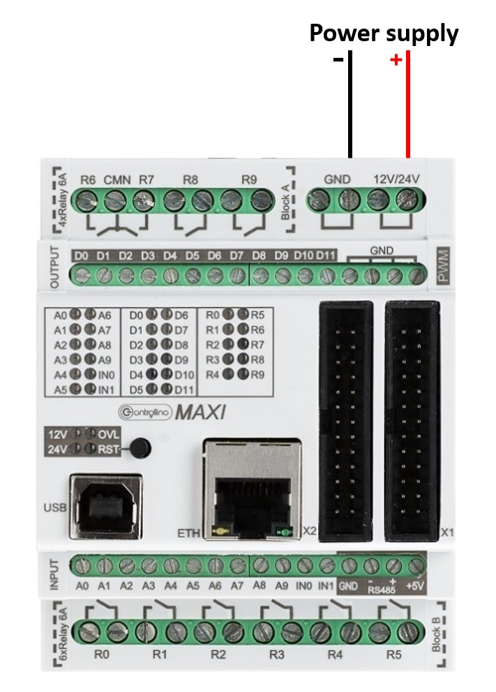
This example shows you how to use our powerful digital outputs and relays. The CONTROLLINO PLCs have “High-Side Switch” outputs, “Half-Bridge” outputs (only MEGA) and potential free relay outputs. Some of these outputs are also capable of generating PWM (Pulse Width Modulation) signals. Therefore it is possible to dim a lamp or to control the speed of a DC motor.
IMPORTANT INFORMATION!
Please, select proper target board in Tools->Board->Controllino MINI/MAXI/MEGA before Upload to your CONTROLLINO.
(Please, refer to https://github.com/CONTROLLINO-PLC/CONTROLLINO_Library if you do not see the CONTROLLINOs in the Arduino IDE menu Tools->Board.)
Note*
Pin header is working on 5V TTL levels. Voltage levels over 5.5V can damage the Controllino permanently.
In case of the Controllino MINI, the relays are connected parallelly to the digital outputs D0-D5 and thus are named D0-D5.
#include <Controllino.h> /* Usage of CONTROLLINO library allows you to use CONTROLLINO_xx aliases in your sketch. */

// the setup function runs once when you press reset (CONTROLLINO RST button) or connect the CONTROLLINO to the PC
void setup() {
 // initialize all used digital output pins as outputs
 pinMode(CONTROLLINO_D0, OUTPUT); // note that we are using CONTROLLINO aliases for the digital outputs
 pinMode(CONTROLLINO_D1, OUTPUT);
 pinMode(CONTROLLINO_D2, OUTPUT); // the alias is always like CONTROLLINO_
 pinMode(CONTROLLINO_D3, OUTPUT); // and the digital output label as you can see at the CONTROLLINO device
 pinMode(CONTROLLINO_D4, OUTPUT); // next to the digital output screw terminal
}

// the loop function runs over and over again forever
void loop() {
 digitalWrite(CONTROLLINO_D0, HIGH); // turn the LED on (HIGH is the voltage level)
 delay(100);                         // wait for 100 milliseconds which is 1/10 of a second
 digitalWrite(CONTROLLINO_D0, LOW);  // turn the LED off by making the voltage LOW
 delay(100);                         // wait for 100 milliseconds which is 1/10 of a second
 digitalWrite(CONTROLLINO_D1, HIGH);
 delay(100);
 digitalWrite(CONTROLLINO_D1, LOW);
 delay(100);
 digitalWrite(CONTROLLINO_D2, HIGH); // please, visit https://www.controllino.com/downloads/
 delay(100);                         // if you want to know more about the mapping of the CONTROLLINO
 digitalWrite(CONTROLLINO_D2, LOW);  // digital outputs to the Arduino pins
 delay(100);
 digitalWrite(CONTROLLINO_D3, HIGH);
 delay(100);
 digitalWrite(CONTROLLINO_D3, LOW);  // by using CONTROLLINO aliases instead of Arduino pin numbers
 delay(100);                         // you ensure sketch portability between all CONTROLLINO variants
 digitalWrite(CONTROLLINO_D4, HIGH);
 delay(100);
 digitalWrite(CONTROLLINO_D4, LOW);
 delay(100);
}
To make the outputs and relays blink, CONTROLLINO pins have to be set up as OUTPUTs!
pinMode(CONTROLLINO_xx, OUTPUT);#include <Controllino.h> /* Usage of CONTROLLINO library allows you to use CONTROLLINO_xx aliases in your sketch.*/
// the setup function runs once when you press reset (CONTROLLINO RST button) or connect the CONTROLLINO to the PC
void setup() {
// initialize all used digital output pins as outputs
pinMode(CONTROLLINO_D0, OUTPUT);
pinMode(CONTROLLINO_D1, OUTPUT); // note that we are using CONTROLLINO aliases for the digital outputs
pinMode(CONTROLLINO_D2, OUTPUT);
pinMode(CONTROLLINO_D3, OUTPUT); // the alias is always like CONTROLLINO_
pinMode(CONTROLLINO_D4, OUTPUT); // and the digital output label as you can see at the CONTROLLINO device
pinMode(CONTROLLINO_R0, OUTPUT); // next to the digital output screw terminal
pinMode(CONTROLLINO_R1, OUTPUT);
pinMode(CONTROLLINO_R2, OUTPUT);
pinMode(CONTROLLINO_R3, OUTPUT);
pinMode(CONTROLLINO_R4, OUTPUT);
}
// the loop function runs over and over again forever
void loop() {
digitalWrite(CONTROLLINO_D0, HIGH); // turn the LED on (HIGH is the voltage level)
delay(100); // wait for 100 milliseconds which is 1/10 of a second
digitalWrite(CONTROLLINO_D0, LOW); // turn the LED off by making the voltage LOW
delay(100); // wait for 100 milliseconds which is 1/10 of a second
digitalWrite(CONTROLLINO_D1, HIGH);
delay(100);
digitalWrite(CONTROLLINO_D1, LOW);
delay(100);
digitalWrite(CONTROLLINO_D2, HIGH); // please, visit https://www.controllino.com/downloads/
delay(100); // if you want to know more about the mapping of the CONTROLLINO
digitalWrite(CONTROLLINO_D2, LOW); // digital outputs to the Arduino pins
delay(100);
digitalWrite(CONTROLLINO_D3, HIGH);
delay(100);
digitalWrite(CONTROLLINO_D3, LOW); // by using CONTROLLINO aliases instead of Arduino pin numbers
delay(100); // you ensure sketch portability between all CONTROLLINO variants
digitalWrite(CONTROLLINO_D4, HIGH);
delay(100);
digitalWrite(CONTROLLINO_D4, LOW);
delay(100);
digitalWrite(CONTROLLINO_R0, HIGH);
delay(100);
digitalWrite(CONTROLLINO_R0, LOW);
delay(100);
digitalWrite(CONTROLLINO_R1, HIGH);
delay(100);
digitalWrite(CONTROLLINO_R1, LOW);
delay(100);
digitalWrite(CONTROLLINO_R2, HIGH);
delay(100);
digitalWrite(CONTROLLINO_R2, LOW);
delay(100);
digitalWrite(CONTROLLINO_R3, HIGH);
delay(100);
digitalWrite(CONTROLLINO_R3, LOW);
delay(100);
digitalWrite(CONTROLLINO_R4, HIGH);
delay(100);
digitalWrite(CONTROLLINO_R4, LOW);
delay(100);
}